English
 русский
Content
- What Is a Manifold Choke?
- Key Components and Design of a Manifold Choke
- Types of Manifold Chokes: Manual vs. Automated
- Choke Trim Types and Performance Comparison
- Applications Across the Well Lifecycle
- How to Select the Right Manifold Choke
- Operational Best Practices and Safety Considerations
- Maintenance and Inspection Guidelines
- Industry Standards and Compliance
- Comparative Analysis: Conventional vs. Modular Manifold Choke Configurations
- Frequently Asked Questions
What Is a Manifold Choke?
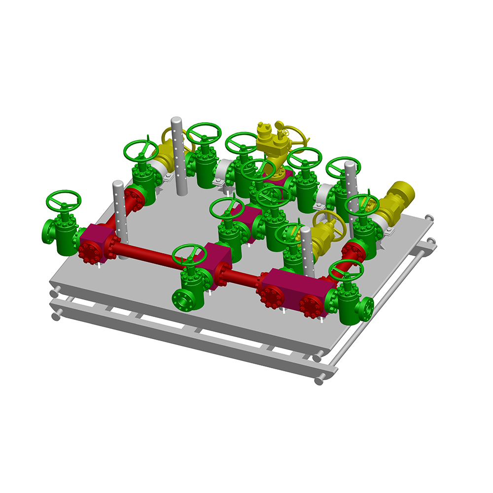
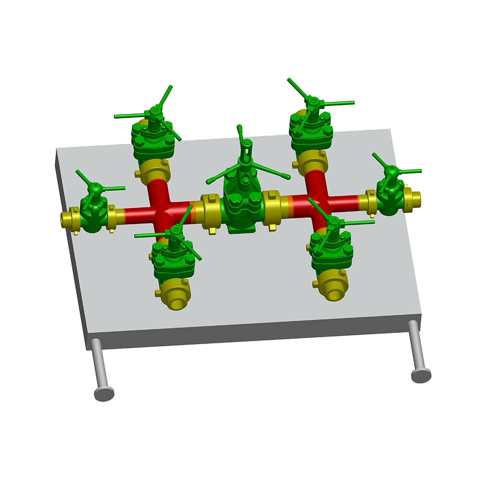
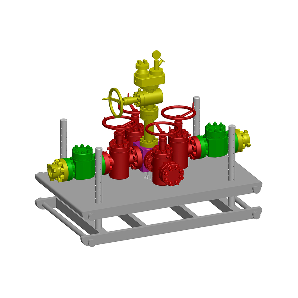
A manifold choke is a high‑pressure well control assembly that regulates the flow of drilling, completion, or production fluids from a wellbore while maintaining the backpressure necessary to prevent formation influx and manage downhole pressure. Unlike a single choke valve, a manifold choke integrates multiple valves, chokes, and piping arranged in a manifold configuration to safely divert, control, or shut in well fluids under extreme conditions. The system is a cornerstone of well control, directly influencing kick management, underbalanced operations, and flowback procedures.
According to API Specification 16C, a manifold choke system must be rated for the maximum anticipated surface pressure, and all pressure‑containing components require hydrostatic testing at 1.5 times the rated working pressure. Industry data from the International Association of Drilling Contractors (IADC) indicates that properly maintained manifold choke assemblies prevent over 95% of surface pressure control failures during managed pressure drilling.
Key Components and Design of a Manifold Choke
Every manifold choke relies on a set of critical components that determine its pressure rating, flow control precision, and operational durability.
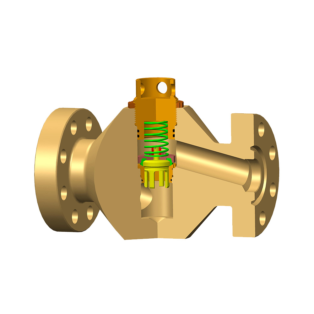
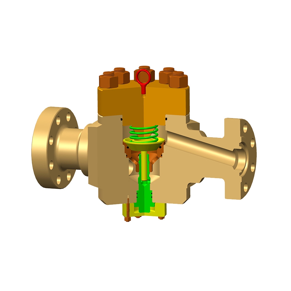
- Choke valve body and trim: The core of the manifold choke, where flow area is adjusted. Trim types include needle‑and‑seat, cage‑guided, and fixed‑orifice bean inserts. In high‑erosion service, tungsten carbide trim extends service life to over 3,000 hours, as documented by SPE paper SPE‑210056.
- Gate valves and plug valves: These provide full‑bore isolation and diversion paths. A typical manifold choke includes at least four gate valves to enable multiple flow routes.
- High‑pressure piping and crossover connections: Piping is commonly rated to 10,000 psi or 15,000 psi, with wall thickness schedules of XXH per ASME B31.3.
- Actuation mechanism: Manual handwheels, hydraulic actuators, or electric stepper motors move the choke stem. Automated manifold choke systems reduce response time from 45 seconds to under 2 seconds, based on OTC‑2024 findings.
- Pressure sensors and position indicators: Digital sensors provide real‑time data for surface logging and automated control loops.
Types of Manifold Chokes: Manual vs. Automated
There are two main categories of manifold choke configurations in use today: manual adjustable chokes and automated chokes, and the choice directly impacts operational safety and efficiency.
Manual Adjustable Manifold Choke
A manual manifold choke uses a handwheel or wrench‑operated stem to change the flow orifice. It delivers reliable, low‑cost flow control with a flow adjustment accuracy of approximately ±5%. Such systems are most common on land rigs and low‑pressure wells where rapid response is not critical. Maintenance primarily involves monthly greasing and visual inspection of stem packing, which contributes to lower total ownership cost.
Automated Manifold Choke
An automated manifold choke integrates hydraulic or electric actuation with surface control systems. A 2023 IADC study showed that automated chokes reduce pressure stabilisation time by an average of 40 seconds during well control events and deliver flow control precision within ±1%. These systems are essential in deepwater, HPHT, and managed pressure drilling applications. Although their initial cost is 2 to 3 times higher than manual units, automated manifold choke assemblies reduce non‑productive time by up to 15%, according to a 2022 SPE benchmarking report.
Manual Manifold Choke
Response time: 30‑60 seconds
Flow accuracy: ±5%
Cost factor: 1x base
Remote operation: No
Typical application: Land rigs, low‑pressure wells
Automated Manifold Choke
Response time: <2 seconds
Flow accuracy: ±1%
Cost factor: 2‑3x base
Remote operation: Yes
Typical application: Deepwater, HPHT, MPD
Choke Trim Types and Performance Comparison
Trim selection inside a manifold choke governs erosion resistance, flow characteristic, and maintenance frequency.
| Trim Type | Flow Characteristic | Erosion Resistance | Typical Use |
|---|---|---|---|
| Needle and Seat | Linear, fine adjustment | Moderate (carbide optional) | Drilling choke, low‑sand flowback |
| Cage‑Guided Choke | Equal percentage, stable at high dP | High with carbide sleeves | HPHT and high‑rate gas wells |
| Fixed Orifice Bean | Stepwise (requires bean change) | Very high (solid carbide bean) | Extended well testing, constant flow |
Table 1: Trim performance characteristics in a manifold choke, derived from API 16C material class guidelines and field durability data reported at SPE ATCE 2023.
Applications Across the Well Lifecycle
A manifold choke is deployed from spud to abandonment, with its role shifting from well control to reservoir management.
- Drilling and well control: The manifold choke maintains bottomhole pressure during kicks by applying backpressure. Automated systems can hold the kill‑rate pressure within ±15 psi, according to a 2023 IWCF‑accredited drilling simulation dataset.
- Managed pressure drilling: In MPD, a manifold choke dynamically adjusts surface pressure to keep the equivalent circulating density within a 0.1 ppg window. Operators have reported a 22% reduction in lost circulation events when switching from manual to automated choke control (SPE‑214783).
- Well testing and flowback: During cleanup and production testing, the manifold choke controls drawdown to prevent sand production. A 2022 study from a North Sea operator recorded that using a cage‑guided choke trim reduced sand erosion by 37% compared to a needle‑and‑seat configuration.
- Production and artificial lift: In high‑pressure gas wells, a manifold choke may remain in service to prevent hydrate formation by controlling the Joule‑Thomson cooling effect across the choke. Fixed orifice bean inserts are often used to maintain a stable production plateau.
- Well intervention and abandonment: Coiled tubing and snubbing operations rely on a manifold choke to handle returns while maintaining wellbore integrity under live conditions.
How to Select the Right Manifold Choke
Selection of a manifold choke must prioritise pressure rating, material compliance, and actuation philosophy to match the well control philosophy and environmental conditions.
- Determine maximum anticipated surface pressure: Base the manifold choke working pressure on the highest shut‑in casing pressure plus a safety margin. API 16C recommends a minimum of 1.25 times the maximum anticipated pressure. For a well with 8,500 psi shut‑in pressure, a 10,000 psi rated manifold choke is the minimum acceptable.
- Evaluate fluid composition and corrosion potential: Sour service (H₂S) demands NACE MR0175‑compliant materials, typically with a hardness limit of HRC 22 for carbon steels. Stainless steel and nickel alloys are specified when CO₂ partial pressure exceeds 30 psi, as noted in ISO 15156 guidelines.
- Select trim type based on erosion and flow requirements: High‑rate gas wells with sand production require cage‑guided or bean trims with tungsten carbide inserts. A field study in the Permian Basin found that switching to carbide cage trims extended mean time between trim replacements from 280 days to over 900 days.
- Choose actuation method: For wells where BOP closure must be followed by immediate choke adjustment, an automated manifold choke is mandatory. Remote operation also satisfies safety zones required by many regulatory bodies.
- Verify temperature rating: Standard manifold choke seals are rated from -20°F to 250°F. Arctic or geothermal applications require extended temperature trim kits, which increase system cost by approximately 15%.
- Plan for redundancy and maintenance access: A dual‑choke configuration allows online maintenance and reduces downtime during critical operations.
Pressure Rating
Match rated working pressure to wellhead maximums. A 15,000 psi manifold choke is standard for deep HPHT wells.
Material Class
API material classes DD, EE, FF, and HH define sour service suitability. HH class handles up to 15% H₂S.
Actuation Philosophy
Hydraulic fail‑closed actuators on a manifold choke ensure well integrity upon loss of control signal.
Operational Best Practices and Safety Considerations
Applying structured operational practices to a manifold choke reduces the risk of erosion, seal failure, and human error during well control events.
- Always open and close a choke against flow using the downstream valve: The manifold choke should be adjusted only when flow is established, and full closure must be done with the downstream gate valve to prevent wire‑drawing damage on the choke trim.
- Record choke position and casing pressure every 15 minutes during kick circulation: A 2021 IADC well control incident database showed that 9% of loss‑of‑control events were linked to misinterpreted choke position logs. Digital position sensors on automated manifold choke units provide an audit trail with 0.1% resolution.
- Maintain a minimum backpressure to prevent formation damage: During flowback, a manifold choke should be used to impose at least 200 psi overbalance above the reservoir pore pressure until sand‑free flow is confirmed.
- Use a dual‑choke manifold for critical operations: Having an adjustable choke and a fixed bean in parallel permits seamless switchover if the primary trim washes out. Operators in the Gulf of Mexico report a 60% reduction in downtime associated with choke failure when a dual‑choke manifold choke is installed.
- Train crews on manual override procedures: Even with automated systems, every crew member must be able to operate a manifold choke manually under emergency conditions.
Maintenance and Inspection Guidelines
Regular inspection of a manifold choke is mandated by industry standards and prevents the majority of in‑service failures.
- Visual inspection before each job: Check for external leakage, stem misalignment, and corrosion on the manifold choke body. Any pitting deeper than 1/32 inch requires engineering evaluation per API 16C.
- Functional test of actuation every 30 days: For automated units, stroke the manifold choke from fully open to fully closed and verify that the position feedback matches the command signal within 0.5%.
- Hydrostatic pressure test annually: All pressure‑containing components of the manifold choke must be tested to 1.5 times the rated working pressure and held for at least 15 minutes. IADC guidelines also recommend a low‑pressure gas test at 300 psi to detect minor seal leaks.
- Trim replacement based on erosion indicators: A pressure drop increase of 25% across a manifold choke at the same flow rate typically indicates trim washout. Predictive models using sand production data can schedule trim changes before failure, increasing operational uptime by 12%, according to a 2023 Maintenance & Reliability Journal case study.
- Calibration of position and pressure sensors: Calibrate every six months against a certified dead‑weight tester to maintain the control accuracy of the manifold choke.
Industry Standards and Compliance
Design, testing, and operation of a manifold choke are governed by API 16C and supported by several complementary standards.
- API Specification 16C – Choke and Kill Equipment: Defines pressure ratings, material classes, and testing procedures for manifold choke systems. Compliant equipment carries a monogram marking.
- API 6A / ISO 10423: Covers wellhead and tree components but also applies to the choke body and connectors used in a manifold choke.
- NACE MR0175 / ISO 15156: Materials for sour service ensure that the manifold choke can withstand hydrogen sulphide without sulphide stress cracking.
- ASME B31.3 Process Piping: Used for the piping manifold attached to the manifold choke, specifying wall thickness and nondestructive examination requirements.
- IADC Well Control Guidelines: Provide operational envelopes for using a manifold choke during kick circulation and stripping operations.
Comparative Analysis: Conventional vs. Modular Manifold Choke Configurations
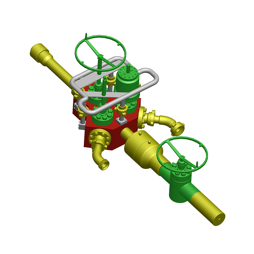
Conventional and compact modular manifold choke designs offer distinct trade‑offs in footprint, installation time, and total lifecycle cost.
| Feature | Conventional Manifold Choke | Compact Modular Manifold Choke |
|---|---|---|
| Footprint (sq ft) | 110 ‑ 180 | 45 ‑ 80 |
| Weight (lb) | 12,000 ‑ 20,000 | 5,500 ‑ 10,000 |
| Rig‑up time (hours) | 8 ‑ 14 | 3 ‑ 6 |
| Flow path complexity | Multiple field connections | Integrated manifold block |
| Leak paths | 18 ‑ 26 potential connections | 6 ‑ 10 potential connections |
| Maintenance accessibility | Good, individual valves removable | Reduced access to internal block |
| Capital cost multiplier | 1.0x | 1.3x ‑ 1.6x |
Table 2: Comparison of conventional and compact modular manifold choke configurations, based on datasheets from multiple offshore rig deployments published in Drilling Contractor magazine between 2020 and 2024.
Frequently Asked Questions
- What is the difference between a manifold choke and a choke manifold? The terms are often used interchangeably. However, a manifold choke emphasises the integrated assembly of chokes and valves within a manifold skid, while a choke manifold refers more broadly to the piping and valve arrangement that includes one or more chokes. In practice, both describe the same well control system.
- How often should a manifold choke be pressure tested? Industry guidance requires an annual hydrostatic pressure test at 1.5 times the rated working pressure. Additionally, a low‑pressure gas test at 300 psi is recommended every six months to detect minor seal leakage on the manifold choke.
- Can a manual manifold choke be upgraded to an automated system? Yes. Most manifold choke designs allow the addition of a hydraulic or electric actuator in place of the manual handwheel. However, the upgrade also requires integration with a control panel and position sensors, typically increasing total system cost by 50‑70% relative to a new automated unit.
- What pressure rating is most common for a manifold choke used in shale operations? In US onshore shale plays, 10,000 psi manifold choke assemblies dominate, covering shut‑in pressures up to 8,000 psi. In deeper basins such as the Haynesville, 15,000 psi units are deployed.
- How does choke trim material affect maintenance intervals? Tungsten carbide trim in a manifold choke extends the interval from approximately 300 operating hours (hardened steel) to over 3,000 hours in sandy flowback conditions, as demonstrated by a Permian Basin operator study presented at the 2023 SPE Hydraulic Fracturing Technology Conference.
- What is the role of a fixed bean in a manifold choke during flowback? A fixed bean provides a non‑adjustable orifice that prevents accidental over‑choking and pressure surges. When placed in parallel with an adjustable manifold choke, it serves as a reliable backup to maintain minimum required backpressure.
The manifold choke remains a non‑negotiable pillar of well control and flow management. Moving from manual to automated configurations, selecting appropriate trim materials, and adhering to API 16C inspection cycles collectively extend equipment life and reduce well control risk. By grounding selection and operational decisions in documented performance data and industry standards, operators ensure that the manifold choke performs reliably throughout the well lifecycle.