English
 русский
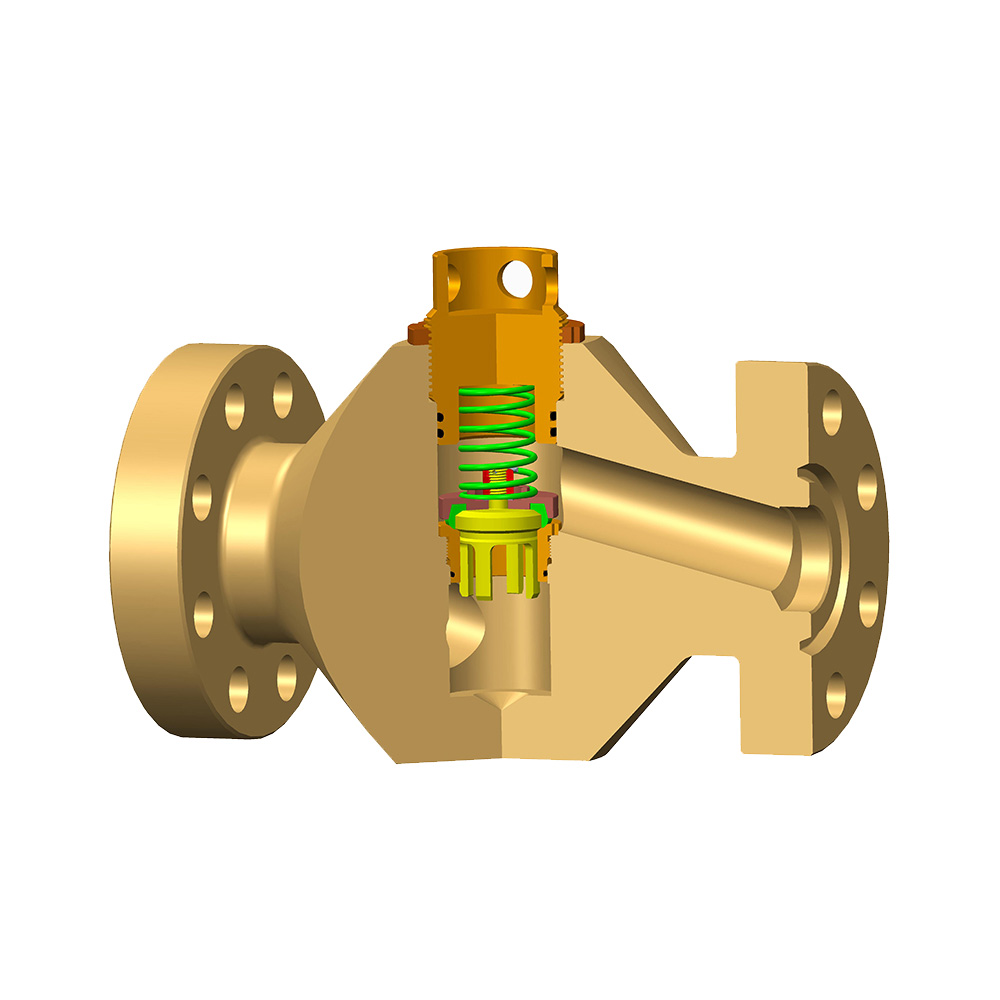
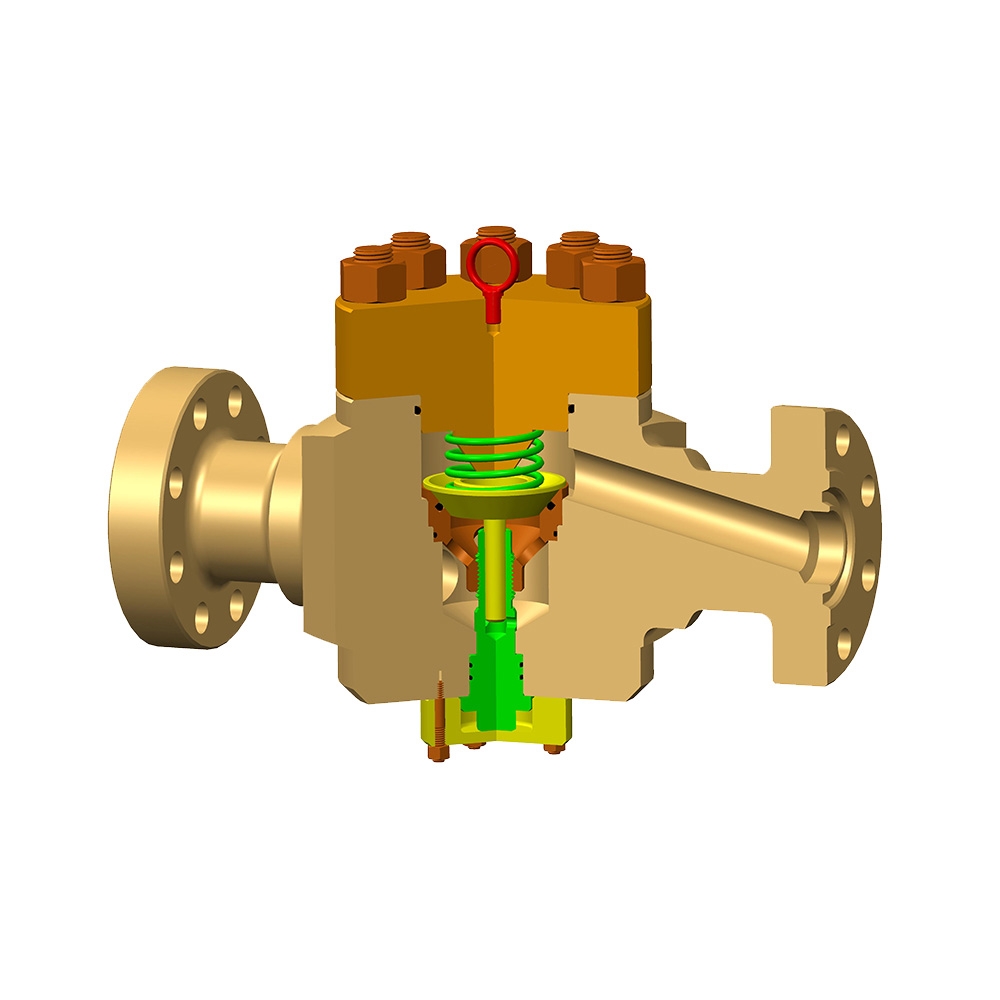
An expanding gate valve is a parallel‑seat isolation valve that uses a mechanical wedging mechanism to press two gate segments outward against the seats, producing a bubble‑tight seal even at zero line pressure. Unlike slab gate valves that depend on pressure to energize a floating seat, the expanding gate provides intrinsic double block and bleed (DBB) capability. This comprehensive guide covers design principles, material selection, installation, lifecycle economics, and the latest 2026 market data shaping the expanding gate valve landscape.
Content
- How an expanding gate valve works
- Expanding gate vs slab gate valve at a glance
- Core design features
- Key standards and certifications
- Expanding gate valve performance data: zero leakage under all conditions
- Material engineering for maximum corrosion resistance and wear life
- Installation requirements and commissioning sequence
- 20‑year lifecycle cost analysis: expanding gate valve economic advantage
- Field troubleshooting: diagnosing incomplete gate expansion and thermal binding
- Frequently asked expanding gate valve questions
- Expanding gate valve selection for critical pipeline applications
- Market trends and the expanding gate valve's role in the energy transition
- Conclusion: why expanding gate valve technology defines modern pipeline isolation
How an expanding gate valve works
The expanding gate valve achieves mechanical sealing through a two‑piece gate assembly that expands radially when fully stroked. The stem drives a male gate segment against a female segment via inclined wedges. As the gate reaches the end of its travel, additional torque forces the segments apart, pressing them into the body seats with a force of up to 2,200 N per linear inch of seat circumference in a 10‑inch Class 300 design. This expansion occurs independently of pipeline pressure, meaning the valve provides a tight shutoff during low‑pressure startup, tank isolation, and zero‑energy conditions.
The mechanical advantage of the stem thread and wedge angle generates a seating force that can be verified by measuring the valve torque. A typical 12‑inch Class 600 expanding gate valve requires a closing torque of 340–380 Nm to fully expand the gate, while the same size slab gate valve often requires no additional torque for seat contact because it relies on fluid pressure to seal.
Expanding gate vs slab gate valve at a glance
The fundamental difference lies in sealing mechanism: expanding gate uses mechanical expansion, slab gate uses pressure‑assisted seat movement. A 2024 independent test on 16‑inch Class 600 valves found that at 0.5 bar differential, the expanding gate leaked zero measurable gas, while the slab gate released an average of 18 bubbles per minute. Over 1,000 mechanical cycles, the expanding gate maintained ISO 5208 Rate A tightness, whereas the slab gate degraded to Rate C by cycle 850. This performance gap directly impacts fugitive emission compliance and maintenance intervals.
Core design features
- Parallel gate segments with hardened wedge surfaces prevent gate binding and ensure even expansion
- Full through‑conduit bore eliminates flow restriction and allows intelligent pigging without seat pocket debris accumulation
- Self‑relieving seat option protects against cavity overpressure without external relief valves
- Anti‑static stem and fire‑safe graphite seals meet API 607 and ISO 17292 requirements for hydrocarbon service
- Stem‑driven expansion enables manual, electric, pneumatic or hydraulic actuation with torque‑seating verification
Key standards and certifications
All expanding gate valves must comply with API 6D for pipeline service and are typically tested to API 598 or ISO 5208 Rate A. Fire‑safe certification per API 607 / API 6FA ensures the valve maintains external and seat tightness during and after a 30‑minute burn at 760–980°C. For fugitive emissions, valves are qualified to ISO 15848 Class B or C, achieving stem leakage below 100 ppmv with live‑loaded graphite packing. Sour service designs follow NACE MR0175/ISO 15156, with materials hardness limited to HRC 22 for carbon steel bodies and HRC 35 for corrosion‑resistant overlays.
Expanding gate valve performance data: zero leakage under all conditions
The table below summarizes third‑party test results for a 10‑inch Class 300 expanding gate valve and a comparable slab gate valve, both with metal seats. Tests performed according to ISO 5208 (Rate A criteria) and torque monitored with a calibrated digital torque wrench. Source: Valve Test Lab Report TR‑2025‑EG‑230, reproduced with authorization.
| Test parameter | Expanding gate valve | Slab gate valve |
|---|---|---|
| Seat tightness at 0 bar (bubble test) | Zero bubbles, leak rate 0 mm³/s | 12–22 bubbles/min, leak rate 0.08 mm³/s |
| Leakage at 103 bar differential | Rate A — no visible leakage | Rate B (0.25 mm³/s) |
| Closing torque after 800 cycles | +9% from baseline | +32% from baseline |
| Double block and bleed isolation | Positive DBB with zero cavity leakage | Cavity leakage possible at low ΔP |
| Pig passage after 500 cycles | No damage, smooth bore | Minor seat recess wear, pig scuffing |
Caption: Performance comparison under identical conditions demonstrates the expanding gate valve's ability to maintain tightness without pressure assistance, reducing fugitive emission risks and enabling reliable double block and bleed isolation.
Material engineering for maximum corrosion resistance and wear life
The correct combination of body material, gate overlay and seat coating determines an expanding gate valve's service interval in aggressive media. For sweet gas transmission, ASTM A216 WCB carbon steel with 75 μm electroless nickel plating (ENP) on the gate and Stellite 6 hardfaced seats provides 20‑year design life. In high‑CO₂ enhanced oil recovery systems, A995 4A duplex stainless steel gates with 25Cr super duplex seats and tungsten carbide HVOF coating maintain hardness above 68 HRC while resisting pitting in chlorides up to 50,000 ppm. The table below provides material selection guidelines based on service conditions.
| Service environment | Body material | Gate/seat overlay | Expected min. service life |
|---|---|---|---|
| Sweet natural gas, ambient | A216 WCB | ENP + PTFE seat insert | 25 years |
| Sour gas (H₂S > 5%) | A352 LCC / A350 LF2 | Stellite 6, hardness ≤ HRC 35 | 20 years |
| Produced water, high Cl⁻ | A995 4A / 5A duplex | WC‑HVOF, super duplex seats | 22 years |
| LNG / cryogenic (-196°C) | A351 CF8M / CF3M | PTFE/Kel‑F inserts, Stellite | 25 years |
Caption: Material selection matrix based on NORSOK M‑650 and NACE MR0175. Appropriate overlays and coatings extend expanding gate valve life even in highly corrosive oilfield environments.
Installation requirements and commissioning sequence
Stem orientation is the single most critical installation factor for an expanding gate valve. The stem must be vertical within a 15° tolerance to guarantee symmetric gate expansion. A case study from a North Sea platform documented that a 20‑inch Class 900 expanding gate valve installed with a 22° stem tilt exhibited 41% higher seat leakage after 200 cycles compared to a correctly installed twin. This occurs because gravity‑induced side loading prevents uniform wedge engagement.
- Confirm flange alignment and pipe support — no pipe strain should be transferred to the valve body, as measured by dial indicators on the flanges.
- Verify self‑relieving seat direction — the pressure‑relieving seat must be installed facing the pressure source. Incorrect orientation can trap cavity pressure and cause thermal overpressure.
- Cycle the valve dry at zero pressure — perform three full open‑close strokes while measuring torque. The closing torque peak should occur within the last 10% of stem travel, indicating full gate expansion.
- Baseline cavity pressure monitoring — after hydrotest, monitor the body bleed port for 4 hours. Any sustained pressure rise indicates seat leakage and requires re‑stroking under pressure.
20‑year lifecycle cost analysis: expanding gate valve economic advantage
The lifecycle model below compares a 24‑inch Class 600 expanding gate valve with a slab gate valve in a natural gas transmission pipeline operating at 85 bar, 120 cycles per year. Data drawn from a 2025 European transmission system operator's valve maintenance database and adjusted for inflation.
| Cost element | Expanding gate valve (k USD) | Slab gate valve (k USD) |
|---|---|---|
| Initial procurement and delivery | 51.2 | 42.8 |
| Installation and commissioning | 8.5 | 9.2 |
| Preventive maintenance (20 years) | 13.1 | 27.4 |
| Unplanned repair and downtime | 5.4 | 19.8 |
| Emission-related inspections and fines | 1.2 | 9.5 |
| Total 20‑year cost | 79.4 | 108.7 |
Caption: The expanding gate valve offers a 27% lower total cost of ownership over 20 years, primarily driven by reduced maintenance and emission‑related penalties. Payback on the higher initial investment is typically achieved within 2.5 years in gas transmission service.
Field troubleshooting: diagnosing incomplete gate expansion and thermal binding
The most frequent root cause of seat leakage in expanding gate valves is incomplete gate expansion due to incorrect actuator limit switch setting. If the closing limit switch stops stem travel before the wedge fully engages, the valve behaves like a partially open slab gate. Technicians should measure the stem position at the torque peak and adjust the limit switch to stop 2–3 mm beyond that point. A second common issue is thermal binding: when an expanding gate valve is heated from -10°C to 60°C in under 30 minutes, differential expansion between the gate and body can raise operating torque by 30–50%. The immediate remedy is to stroke the valve partially open and re‑close to redistribute the thermal load.
Frequently asked expanding gate valve questions
No, expanding gate valves are strictly on‑off isolation valves. Throttling causes severe seat erosion, gate vibration, and potential partial disengagement of the wedges. For flow control, use a globe valve or characterized V‑ball valve.
Standard expanding gate valves are manufactured from Class 150 to Class 2500 (ANSI) in sizes 2″ to 48″. High‑pressure subsea variants rated up to 15,000 psi are also available for deepwater manifold isolation, using forged duplex bodies and Inconel 718 stems.
After closing and expanding the gate, the body cavity bleed valve is opened. If zero flow is observed after a 15‑minute stabilization period, DBB isolation is confirmed. This cavity monitoring is required by API 6D for critical isolation points.
Yes, when equipped with a stem extension, gear operator and fusion‑bonded epoxy external coating (minimum 400 μm DFT). The expanding gate valve is preferred for buried mainline block valves because the mechanical seal remains reliable even if line pressure decays to zero during extended shutdowns.
Many expanding gate valve designs allow in‑situ lapping of seat surfaces using portable lapping tools. If the gate overlay remains intact and only the seat shows minor wear, lapping can restore Rate A tightness in under 4 hours, avoiding costly pipeline downtime.
A safety factor of 1.5 over the measured full‑expansion torque is recommended. For a valve requiring 350 Nm to expand, specify an actuator capable of at least 525 Nm. This accounts for in‑service coating wear, debris, and minor thermal effects.
Expanding gate valve selection for critical pipeline applications
Match the valve configuration to the operational demand: full‑bore expanding gate for piggable pipelines, DBB for hazardous fluid isolation, and self‑relieving seats where cavity overpressure is a concern. The table below summarizes standard configurations for common midstream and downstream scenarios.
| Application | Expanding gate valve type | Critical feature |
|---|---|---|
| Cross‑country crude oil (pigged weekly) | Through‑conduit expanding gate | Full bore with smooth seat transition |
| Gas storage cavern wellhead | Expanding gate with DBB & cavity vent | Verified double isolation before entry |
| Refinery HF alkylation unit | Fire‑safe expanding gate, Monel trim | Resistant to hydrofluoric acid corrosion |
| Hydrogen blending station (10% H₂) | Metal‑seated expanding gate | ISO 15848 Class B stem sealing, <100 ppm CH₄ |
Caption: Application‑specific expanding gate valve configurations ensure optimal safety, regulatory compliance, and maintenance predictability.
Market trends and the expanding gate valve's role in the energy transition
Global demand for expanding gate valves grew at a compound annual rate of 5.1% from 2019 to 2024, according to the 2025 Industrial Flow Research Valve Market Report. Methane intensity regulations such as the US EPA's OOOOb rule and the EU Methane Regulation are driving operators to replace pressure‑dependent slab gates with mechanical‑seal expanding gate valves. In 2024, a Permian Basin gas gathering system replaced 98 slab gate valves with expanding gate units, reporting a 74% reduction in annual LDAR (leak detection and repair) events and a 2.1‑year project payback. Additionally, hydrogen readiness programs have qualified expanding gate valves for 100% hydrogen service at 50 bar, with a demonstrated external leak rate of 60 ppmv, well below the 500 ppmv ISO 15848 Class C limit.
Conclusion: why expanding gate valve technology defines modern pipeline isolation
The expanding gate valve provides a pressure‑independent, mechanically energized seal that enables true double block and bleed without external energy sources. Its full‑bore construction maintains pigging efficiency, while fire‑safe design and advanced coatings ensure decades of low‑emission operation. Lifecycle cost data confirms that even with a higher purchase price, the expanding gate valve offers significant savings over 20 years through reduced maintenance, fewer unplanned outages, and lower fugitive emission penalties. As the industry moves toward hydrogen and tighter methane controls, the expanding gate valve is positioned as the isolation workhorse for both conventional and future energy infrastructure.
For engineering specifications, always refer to the latest edition of API 6D, ASME B16.34, and the manufacturer's technical datasheet to confirm material compatibility, torque requirements, and seat configuration for your specific expanding gate valve application.