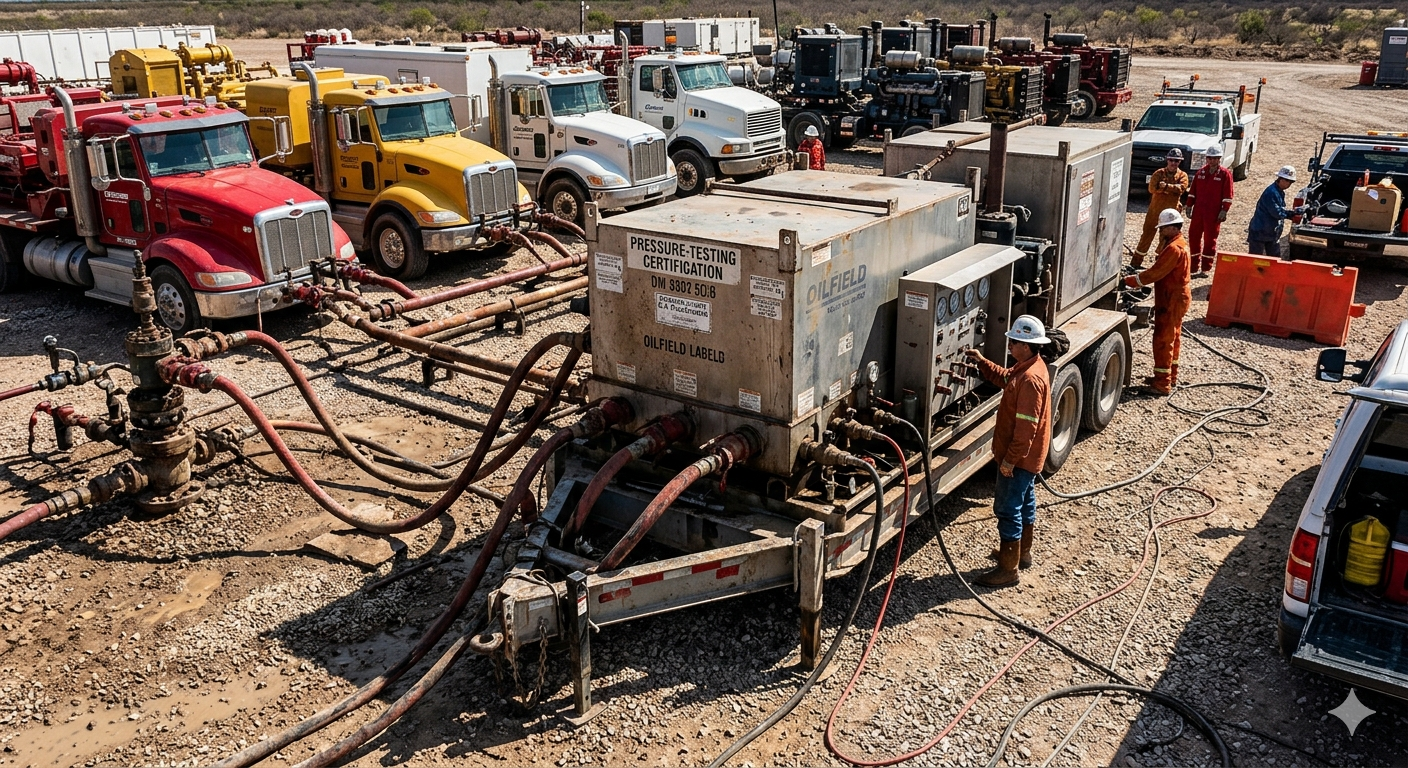
A frac manifold is a high-pressure fluid distribution system used in hydraulic fracturing (fracking) operations to direct, control, and distribute pressurized fracturing fluid from multiple pump trucks to one or more wellheads simultaneously. In short: without a frac manifold, it is physically impossible to coordinate the output of 10–40 high-pressure pumps into a single wellbore at the pressures and flow rates required by modern completion operations. A typical fracturing manifold must handle working pressures of 10,000–20,000 psi and flow rates exceeding 100 barrels per minute (bpm), making it one of the most mechanically demanding pieces of equipment on any well site. This article explains how frac manifolds work, the major design types, selection criteria, operational best practices, and the evolving technology reshaping this critical equipment category.
Content
- What Is a Frac Manifold? Function and Core Components
- Types of Frac Manifolds: Traditional vs. Zipper vs. Combo
- Frac Manifold Pressure Ratings: Selecting the Right Class
- Materials and Metallurgy: What Makes a Frac Manifold Survive High-Pressure Abrasive Service
- Frac Manifold Operations: Rig-Up, Pre-Job Testing, and Stage Execution
- Next-Generation Frac Manifold Technology: Automation and Remote Operation
- Frac Manifold Inspection and Maintenance: What Industry Standards Require
- Frequently Asked Questions: Frac Manifolds
- Conclusion: The Frac Manifold Is the Backbone of Every Modern Completion Operation
What Is a Frac Manifold? Function and Core Components
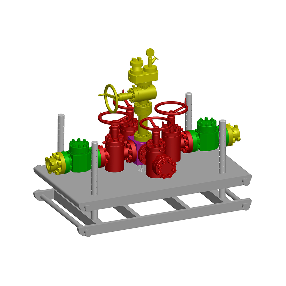
A frac manifold functions as the central fluid hub of a hydraulic fracturing spread — aggregating flow from multiple pump units, providing isolation and flow-control capability, and delivering fluid at controlled pressure to the wellhead treating iron. It is conceptually similar to a highway interchange: multiple lanes of high-volume traffic (pump trucks) merge into a controlled flow path leading to a single destination (the wellbore).
The core function of a fracturing manifold is threefold: fluid distribution, pressure equalization, and operational flexibility. Without a manifold, connecting 20 individual pump trucks directly to a single wellhead would require an unmanageable tangle of high-pressure iron with no way to isolate individual pumps for maintenance, swap between wells without stopping the job, or manage pressure surges from pump startups and shutdowns.
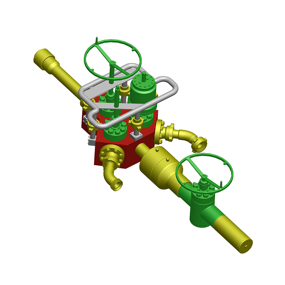
Key Components of a Frac Manifold
- Header body (main bore): The central pipe or forged body through which all fluid flows. Main bore diameters typically range from 4 inches to 7 inches (nominal), with wall thickness engineered to withstand burst pressures of 1.5–2× working pressure. Most header bodies are made from 4130 or 4140 chromoly steel, heat-treated to yield strengths above 100,000 psi.
- Inlet connections (pump side): Individual high-pressure connections where pump truck discharge lines attach. A standard frac manifold has 8–24 inlet ports, each fitted with a plug valve or gate valve for individual pump isolation. Connection types include hammer union (Fig. 1502 or 2002), flanged, or proprietary quick-connect systems.
- Outlet connections (well side): High-pressure outlets leading to the treating iron and wellhead. Multi-well pad operations use manifolds with 2–8 outlet ports to enable simultaneous or sequential treatment of multiple wells without rigging down between stages.
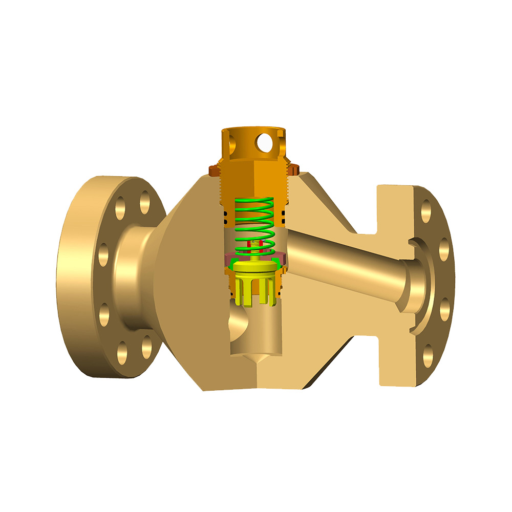
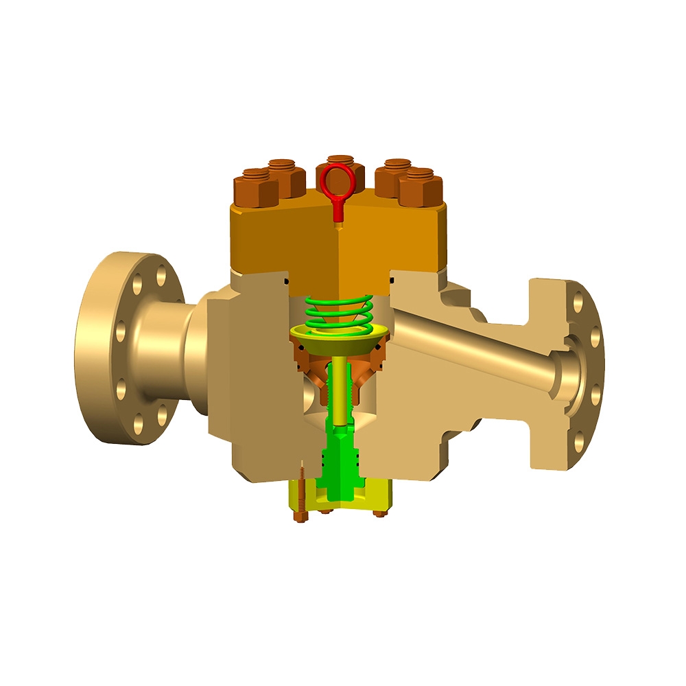
- Isolation valves: Gate valves or plug valves on each inlet and outlet port allow individual isolation of any pump or well connection without shutting down the entire spread. These valves are typically hydraulically or manually actuated, rated for the full manifold working pressure.
- Pressure relief valve (PRV): A safety-critical component that automatically vents fluid if manifold pressure exceeds the maximum allowable working pressure (MAWP). PRVs are typically set at 105–110% of MAWP.
- Pressure gauges and instrumentation ports: Real-time pressure monitoring at multiple points enables early detection of flow restrictions, valve leaks, or pump anomalies. Modern frac manifolds integrate electronic pressure transducers connected to the treatment van's data acquisition system.
- Skid / trailer frame: The manifold assembly is mounted on a steel skid or road-legal trailer for transport and rapid deployment. Trailer-mounted units can be positioned and connected in 45–90 minutes by a standard frac crew.
Types of Frac Manifolds: Traditional vs. Zipper vs. Combo
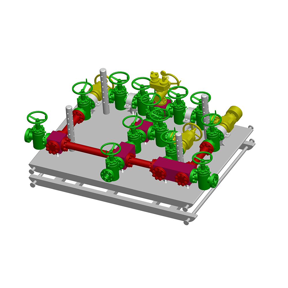
The frac manifold market has evolved from simple single-well headers to sophisticated multi-well systems capable of supporting simultaneous fracturing of adjacent wellbores. Three primary configurations dominate modern operations:
| Parameter | Single-Well Manifold | Zipper Manifold | Combo / Multi-Well Manifold |
|---|---|---|---|
| Wells Served | 1 | 2 (alternating) | 2–8 |
| Typical Inlet Ports | 8–16 | 16–24 | 20–40 |
| Typical Working Pressure | 10,000–15,000 psi | 10,000–15,000 psi | 10,000–20,000 psi |
| Operational Mode | Sequential stages | Alternating between 2 wells | Simultaneous or sequential |
| Rig-Up Time | 45–90 min | 2–4 hrs | 4–8 hrs |
| Pump Utilization | ~60–70% | ~80–90% | ~85–95% |
| Capital Cost (relative) | Low (baseline) | Medium (+40–80%) | High (+100–200%) |
| Best Application | Single-well pads, exploratory | 2-well pads, pad drilling | Multi-well pads, simultaneous frac |
Table 1: Comparison of the three primary frac manifold configurations by key operational and commercial parameters. Zipper and combo manifolds deliver significantly higher pump utilization at the cost of greater complexity and capital investment.
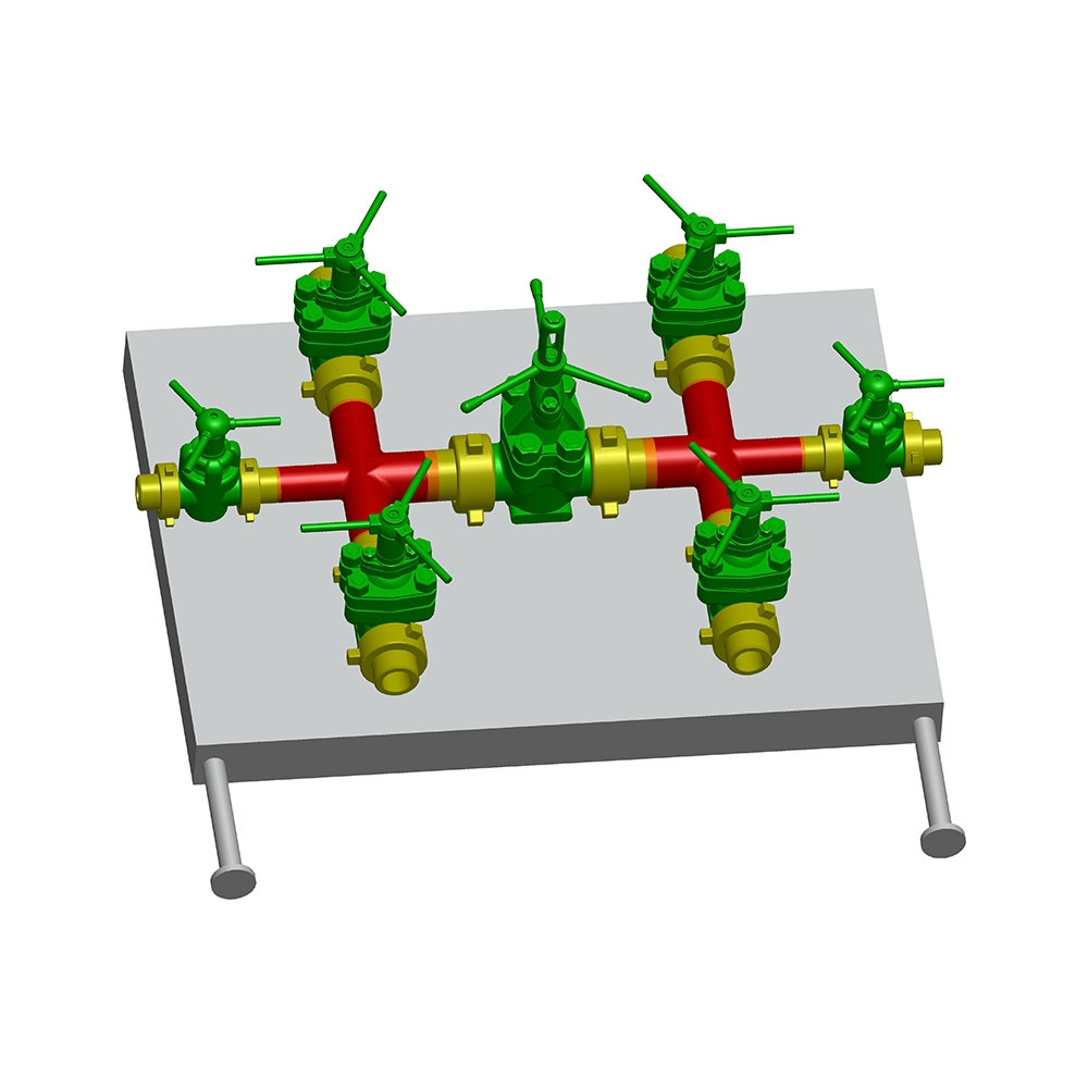
The Zipper Frac Manifold: How It Doubles Pump Efficiency
The zipper frac manifold is the most significant operational innovation in frac manifold design of the past two decades. In a zipper configuration, a single pump spread alternates between two adjacent wellbores — while one well is being fractured, the other is being perforated and prepared for the next stage. This eliminates the non-productive time (NPT) between stages that accounts for 30–40% of total completion time on single-well operations.
The hydraulic advantage is equally significant: research has shown that zipper fracturing on adjacent parallel laterals creates fracture interference patterns that extend total stimulated reservoir volume (SRV) by 15–25% compared to sequential single-well fracturing. The fractures from one well "push" into the reservoir in directions that complement the fracture geometry of the adjacent well, improving drainage efficiency across the pad.
A standard zipper frac manifold consists of two separate header bodies connected by a crossover section with isolation valves, allowing the entire pump spread to be redirected from Well A to Well B by opening and closing two valves — a switching operation that takes less than 60 seconds.
Frac Manifold Pressure Ratings: Selecting the Right Class
Pressure rating is the most safety-critical specification when selecting a frac manifold. Under-specifying pressure rating is the primary cause of catastrophic manifold failures, which can be fatal and result in well control incidents. The industry uses a standardized pressure class system aligned with API 6A and API 16C:
| Pressure Class | Working Pressure (psi) | Test Pressure (psi) | Typical Application | Common Formation |
|---|---|---|---|---|
| 10K | 10,000 | 15,000 | Conventional frac, shallow wells | Permian Basin (some zones) |
| 15K | 15,000 | 22,500 | Standard shale frac, pad drilling | Marcellus, Eagle Ford, Haynesville |
| 20K | 20,000 | 30,000 | Ultra-HPHT, deep wells | Deep Haynesville, SCOOP/STACK |
Table 2: Standard frac manifold pressure classes with corresponding test pressures and typical formation applications. All frac manifold pressure-containing components must be hydrostatically tested to 1.5× working pressure before deployment per API 16C requirements.
The selection of a 15K versus 20K frac manifold is not merely a matter of safety margin — it has direct cost implications. A 20K-rated manifold assembly can cost 40–70% more than an equivalent 15K unit due to the heavier forged bodies, thicker walls, higher-specification valves, and more rigorous material qualification testing required. However, using a 10K or 15K manifold in a formation requiring 18,000+ psi treatment pressure creates an unacceptable risk of pressure containment failure.
Materials and Metallurgy: What Makes a Frac Manifold Survive High-Pressure Abrasive Service
Frac manifold components face a uniquely punishing combination of mechanical stresses: cyclic high-pressure loading during each stage, erosion from high-velocity proppant-laden fluid (sand concentrations of 0.5–4 lb/gal at velocities of 40–80 ft/s), chemical attack from acid pre-flushes and friction reducers, and fatigue from repeated pressurization cycles across hundreds of stages per year.
Body and Header Materials
The main header body of a frac manifold is typically forged from AISI 4130 or 4140 chromoly steel, heat-treated to a minimum yield strength of 75,000–100,000 psi (Grade L or Grade P per API 6A). Forged construction is mandatory — cast iron or welded fabrications cannot reliably withstand the cyclic fatigue loading of frac service. Forging eliminates the internal voids and directional grain weaknesses that make castings susceptible to fatigue cracking.
For sour service applications (H₂S present), materials must meet NACE MR0175 / ISO 15156 requirements, which limit maximum hardness to 22 HRC to prevent sulfide stress cracking. Sour-service frac manifolds use low-alloy carbon steels with controlled chemistry rather than high-strength alloys, accepting lower pressure ratings in exchange for sour resistance.
Erosion Protection Technologies
Proppant erosion is the primary wear mechanism in frac manifold bodies, particularly at tee junctions, elbows, and valve seats where flow velocity and turbulence peak. Three primary erosion mitigation strategies are employed:
- Replaceable wear sleeves: Carbide or hardened steel inserts lining the inner bore at high-erosion zones. These are designed as consumable parts, replaceable during scheduled maintenance without replacing the entire manifold body. A standard wear sleeve has a service life of 200–500 frac stages depending on proppant concentration and type.
- Tungsten carbide valve trim: Gate valves and plug valves in frac service use tungsten carbide seats and trim components with Vickers hardness of 1,500–2,400 HV — far harder than the 100 mesh quartz sand proppant (approximately 800 HV) flowing through them.
- Flow path geometry optimization: Modern frac manifold designs use computational fluid dynamics (CFD) to optimize internal bore geometry, reducing turbulence at junctions by 20–40% and extending mean time between wear-related maintenance.
Frac Manifold Operations: Rig-Up, Pre-Job Testing, and Stage Execution
Proper operational procedure for a frac manifold is as important as equipment specification. The majority of on-location equipment failures are caused by procedural errors — inadequate pressure testing, improper valve sequencing, or connection makeup failures — not by equipment defects.
Pre-Job Pressure Testing Protocol
Every frac manifold assembly must be pressure-tested prior to each job to the maximum anticipated treatment pressure, or to the manifold's rated working pressure, whichever is lower. The standard protocol involves:
- Low-pressure test (200–500 psi): Confirms all connections are properly made up and valves are seated. A 10-minute hold with zero pressure decay required before proceeding.
- High-pressure test (to MAWP or max anticipated treatment pressure): A 10-minute hold at full test pressure with no more than 50 psi decay allowed. Any decay greater than this requires immediate investigation and re-test before operations begin.
- Valve function test: Each isolation valve is cycled open and closed under pressure to verify proper operation. A valve that fails to hold differential pressure is tagged out of service and bypassed or replaced.
- PRV set-point verification: The pressure relief valve pop-off pressure is verified against its certification tag. PRVs in frac service should be re-certified every 12 months or 500 operating hours, whichever comes first.
Stage Execution: Valve Management During a Frac Job
During a fracturing stage, the frac manifold operator is responsible for managing inlet and outlet valve positions in real time. Standard operating procedure requires:
- Never close a downstream (well-side) valve while pumps are running: Closing the well outlet while pumps are at rate creates a "deadhead" condition — pressure spikes to pump shut-in pressure within seconds, potentially exceeding manifold MAWP. All pump units must be shut down before closing well-side valves.
- Sequential pump engagement: Pumps are brought online one at a time through their individual inlet valves, allowing the operator to monitor pressure response and confirm manifold integrity before adding subsequent pumps.
- Zipper manifold switching procedure: When switching between wells in a zipper operation, the receiving well's valve is opened before the treating well's valve is closed — maintaining continuous flow and preventing pressure hammer events that accelerate valve and fitting wear.
Next-Generation Frac Manifold Technology: Automation and Remote Operation
The frac manifold is undergoing a significant technological transformation driven by the industry's push toward remote and autonomous well site operations — a trend accelerated by labor costs, HSE considerations, and the integration of electric fracturing (e-frac) spreads.
Automated Valve Control Systems
Next-generation frac manifolds integrate hydraulically or electrically actuated valves controlled from the treatment van — eliminating the need for personnel to operate manifold valves manually in the high-pressure zone near the wellhead. Automated valve systems can execute the zipper switch sequence in under 5 seconds versus 30–60 seconds for manual operation, reducing NPT and pressure fluctuation during well transitions.
Advanced control systems include interlock logic that prevents operators from inadvertently creating deadhead conditions — if a command to close a well-side valve is issued while pumps are above a pre-set flow rate threshold, the system alerts the operator and requires confirmation before executing the command.
Integrated Sensor Arrays and Predictive Maintenance
Modern frac manifold designs embed ultrasonic wall-thickness sensors at high-erosion zones, transmitting real-time wear data to the treatment van. When wall thickness at a monitored location drops below a preset threshold (typically 80% of original design thickness), the system flags the component for inspection or replacement at the next scheduled maintenance window — before a failure occurs.
Acoustic emission sensors can detect micro-cracking in manifold bodies before cracks propagate to a through-wall condition, providing early warning of fatigue damage that visual inspection would miss. Industry data indicates that predictive maintenance programs based on continuous sensor monitoring can extend average frac manifold service life by 20–35% and reduce unplanned equipment failures by over 60%.
Frac Manifold Inspection and Maintenance: What Industry Standards Require
Frac manifold inspection and maintenance requirements are governed by API RP 7L, API 16C, and operator-specific QA programs. The consequences of manifold failure — high-pressure fluid release, potential ignition, and personnel injury — make compliance non-negotiable.
- Post-job visual inspection: After each frac job, all external surfaces, connection points, valve stems, and pressure gauges are visually inspected for leaks, mechanical damage, erosion grooves, and corrosion. Any fitting showing visible erosion at the OD is removed from service for dimensional inspection.
- Ultrasonic thickness testing (UT): Minimum wall thickness is measured at all high-erosion zones (tee junctions, elbows, valve bodies) using calibrated ultrasonic gauges. Measurements below the calculated minimum wall thickness (per ASME B31.3 or API 6A) require immediate removal from service.
- Magnetic particle inspection (MPI) or dye penetrant testing (DPT): Performed on weld zones, threaded connections, and areas of observed erosion to detect surface-breaking cracks. MPI is preferred for magnetic materials; DPT is used on non-magnetic alloys.
- Full recertification hydrostatic test: Required annually or after any repair, at 1.5× working pressure for a minimum 10-minute hold. Recertification records must be traceable to the specific manifold serial number and retained for the service life of the equipment.
- Valve rebuild and replacement: Gate valves in frac manifold service typically require seat and seal replacement after 150–300 operating cycles (open/close under pressure). Deferred valve maintenance is the leading cause of in-service valve leaks on active frac manifolds.
Frequently Asked Questions: Frac Manifolds
Q1: What is the difference between a frac manifold and a treating iron?
A frac manifold is the central distribution hub that aggregates pump flows and routes them to individual well connections. "Treating iron" refers to the high-pressure pipe segments, hammer unions, and elbows that connect the manifold outlet to the wellhead. The manifold is a fixed assembly mounted on a skid or trailer; treating iron is the field-rigged piping between manifold and wellhead that is configured differently for each job. Both must be rated for the same working pressure, but they serve fundamentally different functions in the flow path.
Q2: How many pump trucks can a frac manifold handle?
Standard frac manifolds are designed with 8–24 inlet ports. A typical large-pad completion in the Permian Basin uses 18–24 pump units, requiring a manifold with at least that many inlet connections. Each inlet port handles the full rated flow rate of one pump truck — typically 25–50 bpm per unit at operating pressure. The manifold's main bore must be sized so that peak total flow (sum of all active pumps) does not produce fluid velocity exceeding 30–40 ft/s, which is the erosion threshold for steel under proppant-laden flow.
Q3: What is a "missile" in frac manifold terminology?
A "missile" (sometimes called a "frac missile" or "missile manifold") is an older, simpler style of frac manifold consisting of a single elongated header body with multiple inlet and outlet ports but minimal integrated valve control. The name comes from the cylindrical shape of the early designs. Modern manifold systems have largely replaced missiles in high-stage-count shale operations due to superior flow control capability, but missiles remain in use for simpler conventional frac operations where cost minimization is the primary driver.
Q4: How does a frac manifold handle the pressure surge when a pump is added or removed?
When a pump is added to the spread, its outlet valve on the frac manifold is opened slowly — not snapped open — while the pump is brought to line pressure before connecting to the manifold. This "soft connect" procedure, which takes 10–30 seconds, prevents a hydraulic hammer event that would occur if a high-pressure pump were suddenly connected to a manifold at different pressure. Modern automated manifold systems include inlet valve pressure equalization logic: the valve will not open fully until the pressure differential across it drops below 500 psi, ensuring a smooth pressure transition.
Q5: What certifications should a frac manifold carry?
A properly certified frac manifold should carry documentation for: API 6A or API 16C pressure rating compliance for all pressure-containing components; material test reports (MTRs) tracing all pressure-containing parts to their heat and lot numbers; hydrostatic test certificate signed by a qualified inspector; valve performance test certificates; and, where applicable, NACE MR0175 compliance documentation for sour service. Some operators additionally require third-party equipment inspection (TPEI) by a recognized inspection body before deployment on their locations.
Q6: How is a frac manifold different from a production manifold?
While both are fluid distribution systems, a frac manifold and a production manifold are fundamentally different in design and service requirements. A frac manifold is a temporary, high-pressure (10,000–20,000 psi) system designed for short-duration, cyclic pump service with abrasive proppant-laden fluids. A production manifold is a permanent, lower-pressure (typically 1,000–5,000 psi) system designed for continuous steady-state flow of produced hydrocarbons. Production manifolds prioritize corrosion resistance and long-term sealing; frac manifolds prioritize pressure rating, erosion resistance, and rapid field reconfiguration.
Conclusion: The Frac Manifold Is the Backbone of Every Modern Completion Operation
A frac manifold is far more than a passive piece of pipe — it is the hydraulic command center of a hydraulic fracturing spread, and its specification, maintenance, and operation directly determine job efficiency, personnel safety, and completion quality. Selecting the right manifold type (single-well, zipper, or combo), pressure class (10K, 15K, or 20K), and material specification for your formation and operating conditions is a technical decision with major cost and safety consequences.
The data makes a compelling case for investing in high-quality frac manifold equipment: zipper manifolds reduce completion NPT by 30–40%, automated valve systems cut manifold-related incidents by over 60%, and predictive maintenance programs extend equipment service life by 20–35%. As the industry continues to push toward higher pump counts, higher treatment pressures, and simultaneous multi-well operations, the fracturing manifold will only become more central — and more technically demanding — in the completion equipment stack.