In industrial fluid systems, particularly within demanding sectors like oil and gas production, chemical processing, and power generation, precise control over fluid flow is paramount. The choke valve serves as a critical component specifically engineered for this purpose. Unlike standard isolation or throttling valves designed primarily for on/off service or moderate flow regulation, the choke valve is optimized to create a controlled, significant pressure drop and manage high-velocity, often erosive or corrosive, fluid streams.
The Core Principle: Inducing Pressure Drop
The fundamental mechanism by which a choke valve controls flow is through the deliberate creation of a restriction within the flow path. This restriction forces the fluid to accelerate as it passes through a narrowed orifice or gap. According to Bernoulli's principle, this increase in velocity results in a corresponding decrease in the fluid's pressure energy downstream of the restriction – a phenomenon known as a pressure drop.
-
Upstream Pressure (P1): The pressure of the fluid entering the choke valve.
-
Downstream Pressure (P2): The pressure of the fluid exiting the choke valve.
-
Pressure Drop (ΔP): The difference between P1 and P2 (ΔP = P1 - P2).
-
Flow Rate (Q): The volumetric quantity of fluid passing through the valve per unit time.
The relationship between flow rate (Q), the size of the restriction (orifice area, A), and the pressure drop (ΔP) is governed by the basic flow equation for incompressible fluids (simplified):
Q = C_d * A * √(2 * ΔP / ρ)
Where:
-
C_dis the discharge coefficient (accounting for friction and flow characteristics) -
ρis the fluid density
This equation highlights the direct influence of the orifice area (A) and the pressure drop (ΔP) on the flow rate (Q). By adjusting the effective orifice area within the choke valve, operators directly control the magnitude of the pressure drop and, consequently, the flow rate of the fluid.
Key Mechanisms and Design Variations
Choke valves achieve this controlled restriction through different internal designs:
-
Fixed Chokes: These feature a non-adjustable orifice (e.g., a bean or insert with a precisely machined hole). Flow control is achieved by selecting and installing a specific bean size that creates the desired pressure drop for the expected flow conditions. They are simple, robust, and used where flow rates are relatively stable.
-
Variable Chokes: These allow for real-time adjustment of the orifice area, enabling dynamic flow control in response to changing process conditions. Common designs include:
-
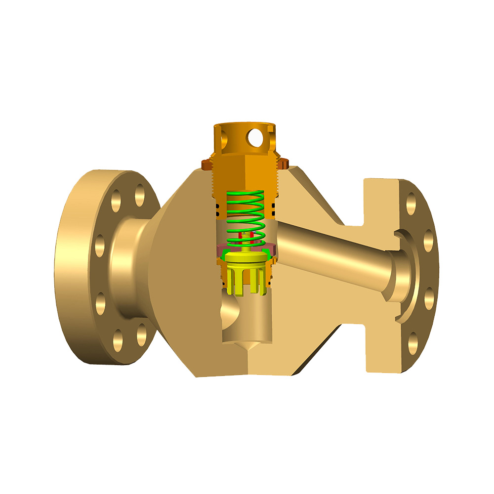
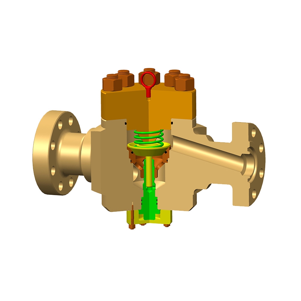
Needle and Seat: A tapered needle moves linearly into or out of a matching seat, gradually changing the annular flow area.
-
Cage and Plug: A perforated cage surrounds a cylindrical or tapered plug. Moving the plug alters the open area of the cage ports.
-
Rotary Discs: Multiple discs with aligned or offset holes rotate relative to each other to vary the open flow area.
-
Operational Functions and Critical Applications
The ability to control flow via induced pressure drop gives the choke valve several vital functions:
-
Flow Rate Regulation: The primary function – precisely setting and maintaining the desired volumetric or mass flow rate of production fluids (oil, gas, water mixtures), process chemicals, or cooling water.
-
Backpressure Maintenance: Chokes are essential for maintaining sufficient pressure upstream of the valve. This is critical in oil and gas wells to control reservoir drawdown, prevent sand production, avoid formation damage (like water coning), and ensure stable flow from the reservoir into the wellbore.
-
Pressure Control: By managing the pressure drop, chokes directly influence downstream system pressure. They protect downstream equipment (separators, pipelines, processing facilities) from overpressure conditions originating upstream.
-
Energy Dissipation: Safely dissipates the energy of high-pressure fluids before they enter lower-pressure systems.
Critical Considerations for Choke Valve Performance
The effectiveness and longevity of a choke valve depend heavily on addressing inherent challenges:
-
Erosion: High-velocity fluids, especially those containing abrasive solids (sand, proppant), rapidly erode valve internals (seats, plugs, cages, orifices). Materials like tungsten carbide, Stellite, or ceramic coatings are commonly used for erosion resistance.
-
Cavitation: If the downstream pressure (P2) drops below the fluid's vapor pressure, vapor bubbles form. These bubbles implode violently when pressure increases downstream, causing surface pitting and damage. Choke trim designs aim to minimize cavitation potential.
-
Corrosion: Compatibility with corrosive fluids (H₂S, CO₂, acids) dictates material selection (e.g., corrosion-resistant alloys - CRAs).
-
Flashing: Occurs when the downstream pressure is below the fluid's bubble point pressure, causing a portion of the liquid to flash into vapor. This two-phase flow alters flow characteristics and can exacerbate erosion.
-
Noise and Vibration: High-pressure drops can generate significant noise and vibration, requiring mitigation strategies like multi-stage pressure reduction trim or external silencers.
The choke valve is an indispensable component for precise fluid flow control in critical industrial applications. By creating a calibrated restriction, it leverages the fundamental relationship between pressure drop and flow rate. Whether through a fixed orifice or an adjustable mechanism, the choke valve enables operators to regulate flow, maintain essential backpressure, control system pressures, and safely manage the energy of process fluids. Understanding the principles of pressure drop, selecting the appropriate valve type (fixed or variable), and carefully considering material choices to combat erosion, corrosion, and other challenges are essential for the reliable and effective operation of choke valves in demanding service environments. Their robust design and focused functionality make them the engineered solution for critical flow control tasks where standard valves fall short.