A hydraulic choke manifold is a pressure-control assembly installed on a wellhead that uses hydraulically actuated choke valves to regulate and restrict the flow of wellbore fluids during drilling, well control, and well kill operations. By precisely managing backpressure on the annulus, a hydraulic choke manifold is the last line of engineered defense between a manageable kick and a full-scale blowout. Every oil and gas well drilled to pressures above 3,000 PSI is required by regulation in most jurisdictions to have a certified choke manifold in service — and on high-pressure, high-temperature (HPHT) wells, the hydraulic choke manifold is universally preferred over manual alternatives due to its remote-operation capability and faster response time.
Content
- What Is a Hydraulic Choke Manifold and What Does It Do?
- How Does a Hydraulic Choke Manifold Work? The Core Mechanics
- Which Types of Hydraulic Choke Manifold Configurations Exist?
- Hydraulic vs. Manual Choke Manifold: Which Is the Right Choice?
- What Are the Key Components of a Hydraulic Choke Manifold?
- What Specifications and Standards Govern a Hydraulic Choke Manifold?
- Why Hydraulic Choke Manifold Maintenance Is Non-Negotiable
- Frequently Asked Questions About Hydraulic Choke Manifolds
- Conclusion: Why the Hydraulic Choke Manifold Is the Cornerstone of Well Control
What Is a Hydraulic Choke Manifold and What Does It Do?
A hydraulic choke manifold is a network of high-pressure pipes, valves, chokes, gauges, and instrumentation designed to control wellbore fluids exiting through the choke line while maintaining a precise and adjustable backpressure on the formation. It sits downstream of the BOP (Blowout Preventer) stack and upstream of the mud gas separator or shale shaker system.
During normal drilling, the mud column provides primary well control through hydrostatic pressure. When an unexpected influx of formation fluid — called a kick — enters the wellbore, the driller closes the BOP and diverts flow through the choke manifold. The hydraulic choke manifold then allows the crew to circulate out the kick while maintaining sufficient backpressure to prevent further formation fluid influx, using the choke valve opening to fine-tune annular pressure in real time.
The "hydraulic" designation specifically refers to the actuation mechanism: rather than turning a handwheel manually, an operator at a remote console sends hydraulic fluid pressure to a cylinder that opens or closes the choke bean (the internal restriction element) with precision and speed. On an HPHT well where pressures can spike from 5,000 PSI to 15,000 PSI in seconds, the ability to respond in under 2–3 seconds from a safe distance is not a convenience — it is a critical safety requirement.
How Does a Hydraulic Choke Manifold Work? The Core Mechanics
A hydraulic choke manifold works through three integrated subsystems: the pressure-rated flow path (the manifold body), the hydraulically actuated choke valves, and the remote control panel — all working in concert to regulate wellbore backpressure with precision.
1. The Manifold Body and Flow Path
The manifold body consists of heavy-wall carbon steel or alloy steel piping rated to the working pressure of the well — typically 5,000 PSI, 10,000 PSI, or 15,000 PSI working pressure (WP), with test pressures of 1.5× WP. The body includes inlet flanges (connecting to the choke line from the BOP), multiple parallel choke valve paths (typically two adjustable chokes and two fixed chokes in a standard 4-choke configuration), wing valves, kill line connections, pressure gauges, and outlet connections to the mud-gas separator and flare line.
Parallel choke paths are not redundant in the conventional sense — they serve distinct operational roles. The adjustable hydraulic chokes handle primary well kill operations where fine flow control is essential. The fixed (positive) chokes are pre-set to a specific orifice diameter and used when a known, stable backpressure is required without continuous adjustment.
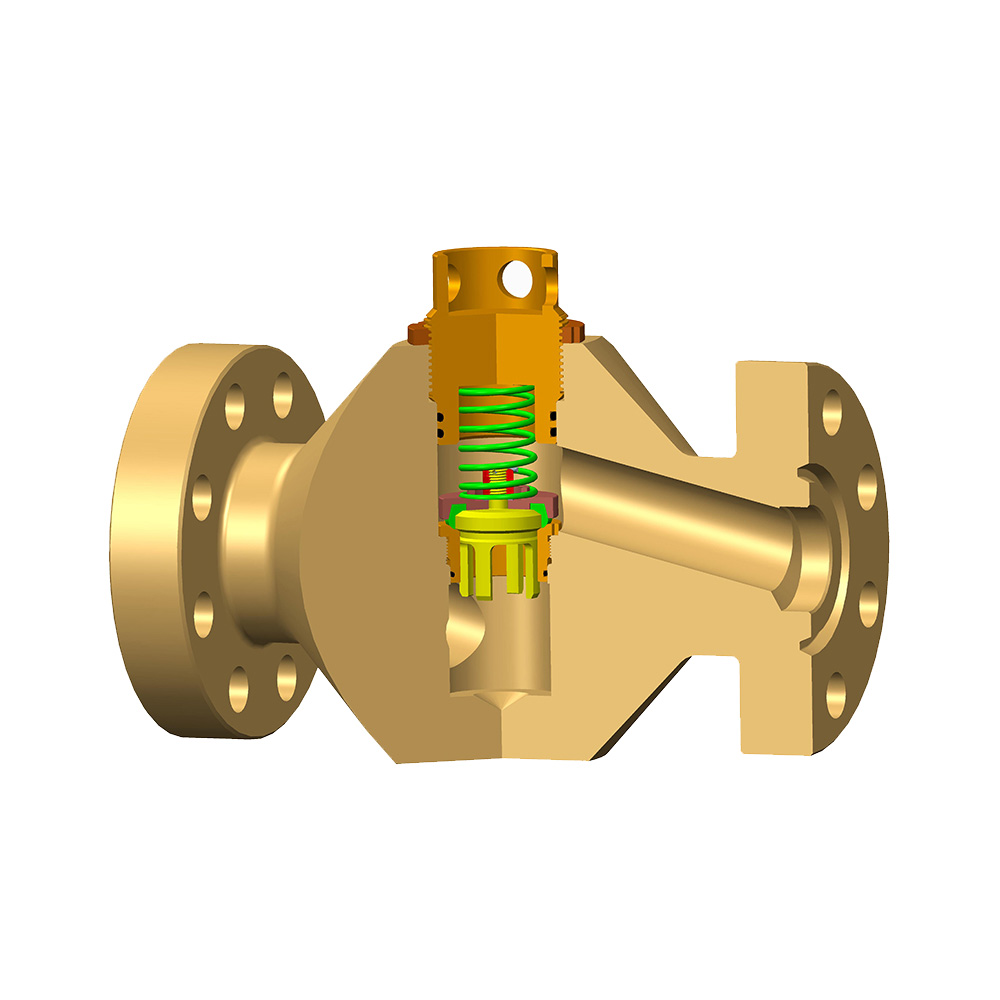
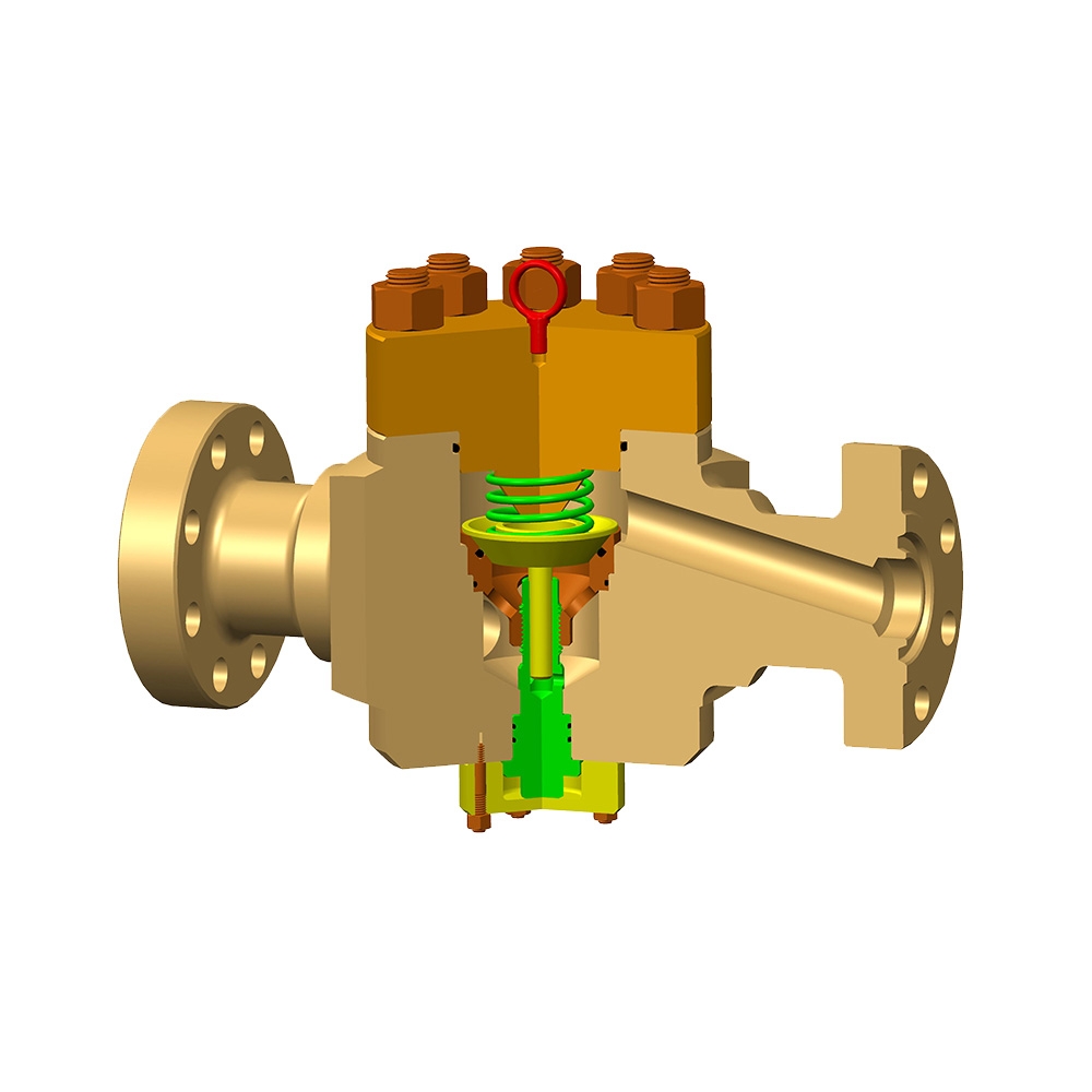
2. The Hydraulic Choke Valve
The hydraulic choke valve is the heart of the manifold — a high-erosion-resistant assembly containing a tungsten carbide or ceramic choke bean whose effective orifice area is controlled by a hydraulic actuator cylinder. As the actuator extends or retracts (driven by hydraulic fluid at typically 1,500–3,000 PSI supply pressure), it moves the choke bean relative to a fixed seat, varying the annular flow area from fully closed (zero flow) to fully open (maximum flow).
The relationship between choke position and downstream pressure is governed by the choke flow equation. For incompressible (liquid-dominant) flow, downstream pressure is approximately proportional to the square of flow velocity through the orifice. For gas-dominant kicks, the flow can become choked (sonic) — a critical flow condition where downstream pressure changes no longer affect upstream (annular) pressure, which is an important consideration during gas kick circulation.
3. The Remote Control Panel
The remote hydraulic control panel — typically positioned at the driller's console or a dedicated choke operator station 20–50 feet from the manifold — provides real-time pressure readouts and direct choke position control without requiring personnel to be near the high-pressure manifold body. Modern panels include digital casing pressure gauges, drill pipe pressure gauges, choke position indicators (0–100% open), stroke counters for the mud pump, and in advanced systems, automated pressure-hold logic that maintains a target casing pressure setpoint without continuous manual adjustment.
Which Types of Hydraulic Choke Manifold Configurations Exist?
Hydraulic choke manifolds are configured primarily by working pressure rating and choke count — the two variables that most directly determine operational capability and cost.
| Configuration | Working Pressure | Choke Count | Typical Application |
| Standard 2-Choke | 5,000 PSI | 1 hydraulic + 1 fixed | Onshore shallow wells, work-overs |
| Standard 4-Choke | 5,000 / 10,000 PSI | 2 hydraulic + 2 fixed | Most onshore and offshore applications |
| HPHT 4-Choke | 15,000 PSI | 2 hydraulic + 2 fixed | Deep gas wells, HPHT formations |
| Subsea Choke Manifold | 10,000–15,000 PSI | 2–4 hydraulic (ROV-operated) | Deepwater and ultra-deepwater drilling |
| MPD Choke Manifold | 5,000–15,000 PSI | 2–4 hydraulic (automated) | Managed Pressure Drilling operations |
Table 1: Common hydraulic choke manifold configurations by working pressure, choke count, and primary operational application.
Hydraulic vs. Manual Choke Manifold: Which Is the Right Choice?
For any well with a surface shut-in casing pressure exceeding 3,000 PSI or a maximum anticipated surface pressure above 5,000 PSI, a hydraulic choke manifold is strongly preferred over a manual design — and may be legally required under API 16C and regional drilling regulations.
| Attribute | Hydraulic Choke Manifold | Manual Choke Manifold |
| Actuation Speed | 2–5 seconds (full travel) | 15–60+ seconds (operator-dependent) |
| Remote Operation | Yes (up to 50 ft standard; longer with add-ons) | No — operator must be at the manifold |
| Pressure Control Precision | ±10–25 PSI with skilled operator | ±50–150 PSI typical |
| Operator Safety | High — remote console away from pressure | Lower — proximity to live high-pressure lines |
| Automation Compatibility | Yes (MPD integration possible) | No |
| Upfront Cost | Higher ($80,000–$500,000+) | Lower ($15,000–$80,000) |
| Best Application | HPHT, offshore, MPD, deep gas wells | Low-pressure onshore wells, workover operations |
Table 2: Hydraulic choke manifold versus manual choke manifold — performance, safety, and cost comparison for drilling operations.
What Are the Key Components of a Hydraulic Choke Manifold?
A hydraulic choke manifold consists of eight core component categories — each of which must be individually rated, tested, and certified to the manifold's maximum allowable working pressure (MAWP).
- Choke body and flow cross: The structural backbone. Typically forged from AISI 4130 or 4140 alloy steel, heat-treated to minimum 75,000 PSI yield strength. API 16C mandates full material traceability and certified impact testing at operating temperatures.
- Hydraulic adjustable choke valve: Contains the choke bean, seat, stem, and actuator cylinder assembly. Tungsten carbide (WC) trim is standard for abrasive fluid service; silicon carbide or ceramic trim is selected for highly corrosive or extremely abrasive environments (e.g., sand-laden gas). Bean diameters range from 1/64" to 2" effective orifice.
- Fixed positive choke: A simple, non-adjustable orifice plate or bean held in place by a threaded retainer. Available in 1/64" orifice increments. Used as the backup choke path when the adjustable choke requires maintenance or when a stable, pre-calculated backpressure is needed.
- Gate valves (wing valves): API 6A or API 16C rated gate valves control flow routing to individual choke paths. Full-bore designs minimize pressure drop and prevent solids from accumulating in the valve cavity. Typically rated to the same WP as the manifold body.
- Pressure gauges and transducers: Analog Bourdon tube gauges (typical range: 0–15,000 PSI) for immediate visual reference, backed by electronic pressure transducers for data logging and remote display. Dual-element transducers are standard on offshore units for redundancy.
- Hydraulic power unit (HPU): A self-contained pump, reservoir, accumulator, and control valve assembly that supplies hydraulic actuation fluid (typically mineral oil or water-glycol) to the choke actuators at regulated supply pressure. Accumulators store sufficient energy for at least 3 full choke cycles without HPU power, per API 16D requirements.
- Remote control console: The operator interface, containing choke position control levers or dials, pressure gauge displays, pump stroke counter, and alarm indicators. Connected to the manifold via high-pressure hydraulic hose bundles and instrumentation cables.
- Kill line and relief valve connections: Ports on the manifold body that allow connection to the mud pump (for bullheading or kill operations) and pressure relief valves that protect the system from over-pressure events above the MAWP.
What Specifications and Standards Govern a Hydraulic Choke Manifold?
Every hydraulic choke manifold used in oil and gas drilling must comply with API Specification 16C (Choke and Kill Equipment), which sets minimum requirements for design, materials, testing, marking, and documentation.
API 16C defines three performance requirement levels (PRL) for choke and kill systems, ranging from PRL 1 (least demanding — low-pressure onshore) to PRL 3 (most demanding — offshore HPHT). Additionally, all pressure-containing components must pass:
- Factory Acceptance Test (FAT): Hydrostatic shell test at 1.5× MAWP for a minimum of 15 minutes with zero leakage permitted. Function test of all valves and choke actuators through full travel under pressure.
- Low-pressure seal test: 200–300 PSI nitrogen or water test after the high-pressure test to verify seat and stem seal integrity at low differential pressure — a condition that often reveals seal defects that high-pressure tests mask.
- Material traceability: All pressure-containing parts must have full mill certifications traceable to the heat of steel. Charpy impact tests at the minimum design temperature (MDT) — which can be as low as -60 °F (-51 °C) for arctic applications — are required for PRL 2 and PRL 3 equipment.
- NACE MR0175 / ISO 15156 compliance: For sour service (H₂S-containing wells), all wetted materials must meet sulfide stress cracking (SSC) resistance requirements. This typically limits hardness to ≤22 HRC for carbon and low-alloy steels.
| Standard | Scope | Key Requirement |
| API 16C | Choke & Kill Equipment | Design, material, testing, PRL classification |
| API 6A | Wellhead & Tree Equipment | Gate valve design & testing requirements |
| API 16D | BOP Control Systems | HPU accumulator sizing, redundancy |
| NACE MR0175 | Sour Service Material | SSC resistance, hardness limits for H₂S service |
| ISO 13533 | Drilling & Well Servicing | International equivalent to API 16C |
Table 3: Key industry standards governing hydraulic choke manifold design, testing, and material requirements for oil and gas drilling operations.
Why Hydraulic Choke Manifold Maintenance Is Non-Negotiable
Hydraulic choke manifold failures during a well control event are among the most dangerous scenarios in drilling — and most failures trace back to deferred maintenance, improper erosion monitoring, or incorrect fluid compatibility rather than design flaws.
The choke bean and seat are the highest-wear components in the entire system. High-velocity fluid carrying sand, barite, or drill cuttings at pressures of 10,000+ PSI erodes tungsten carbide trim at rates that depend exponentially on flow velocity. Industry data indicates that a 10% increase in flow velocity through a choke produces approximately a 33% increase in erosion rate. On wells with high sand production, bean replacement may be required after as few as 8–12 hours of active circulation at high flow rates.
- Daily checks: Hydraulic fluid level in the HPU reservoir, hydraulic supply pressure, function-test of choke actuation through full travel (open-close-open), visual inspection of all gauge connections and hose fittings for seeps or weeps.
- Weekly inspection: Actuator stem packing leak-off check, gate valve stem grease injection (one full shot per valve per week minimum in most OEM guidelines), pressure gauge calibration verification against a certified reference gauge.
- After each well control event: Full disassembly and measurement of choke bean internal diameter using a calibrated bore gauge. Any bean showing more than 5% increase in orifice diameter compared to nominal should be replaced before the next operation.
- Annual overhaul: Full pressure-rated hydrostatic re-test at 1.5× MAWP, replacement of all elastomeric seals (O-rings, packing), non-destructive examination (UT thickness measurement) of the manifold body flanges and pipe spools, and hydraulic fluid analysis for contamination and viscosity degradation.
Frequently Asked Questions About Hydraulic Choke Manifolds
Q: What is the difference between a choke manifold and a kill manifold?
A: A choke manifold controls fluid exiting the wellbore (from the annulus), while a kill manifold delivers high-pressure drilling fluid into the wellbore (typically into the casing or kill line port of the BOP). In a complete well control system, both are present and connected to different ports on the BOP stack. The hydraulic choke manifold is used to manage backpressure during kick circulation; the kill manifold is used for bullhead kills and for delivering weighted mud to the wellbore. Some integrated assemblies combine both functions in a single skid frame.
Q: How many chokes does a standard hydraulic choke manifold have?
A: The most common configuration is a 4-choke manifold: two hydraulically adjustable chokes and two fixed positive chokes. The dual adjustable chokes provide redundancy — if one choke is being serviced or fails, flow can be routed to the second without interrupting well control operations. The two fixed chokes serve as backup paths for pre-calculated pressure management and emergency use. Smaller workover operations may use a 2-choke configuration, while complex HPHT or MPD operations sometimes employ 6-choke assemblies.
Q: What working pressure rating do I need for my hydraulic choke manifold?
A: Your hydraulic choke manifold working pressure rating must equal or exceed the maximum anticipated surface pressure (MASP) for the well, which is calculated as the maximum formation pressure minus the hydrostatic pressure of a column of fresh water to surface. As a practical guideline: wells with MASP up to 5,000 PSI use a 5,000 PSI manifold; 5,001–10,000 PSI MASP requires a 10,000 PSI manifold; above 10,000 PSI MASP, a 15,000 PSI manifold is required. Always consult your well control program and regulatory authority — selecting an under-rated manifold is an unacceptable safety risk.
Q: Can a hydraulic choke manifold be used for Managed Pressure Drilling (MPD)?
A: Yes — but standard hydraulic choke manifolds require significant upgrades to serve as MPD choke systems. MPD applications require choke valves with finer position resolution (typically 0.1% increments versus 1% for well control chokes), faster actuation speeds (under 1 second for full-travel in some MPD systems), automated control integration with the surface backpressure pump, and rotating control device (RCD) compatibility. Purpose-built MPD choke manifolds incorporate PLC-based automated pressure control that can hold annular backpressure within ±15 PSI of setpoint — a level of precision not achievable with a standard hydraulic well control manifold.
Q: What material should I specify for sour (H₂S) service applications?
A: For sour service, all wetted metallic components must comply with NACE MR0175 / ISO 15156, which generally limits hardness to ≤22 HRC for carbon and low-alloy steels and requires specific alloy selections for higher-strength components. Body and bonnet materials are typically AISI 4130 normalized and tempered (not quenched and tempered to high strength levels), while choke beans shift from standard tungsten carbide to NACE-compliant cobalt-binder formulations. Elastomeric seals must be selected for H₂S compatibility — Viton (FKM) is common for moderate sour service; HNBR or FFKM is specified for severe sour and high-temperature combinations. Always provide the maximum H₂S partial pressure and temperature to the manufacturer when specifying a sour service hydraulic choke manifold.
Q: How often should a hydraulic choke manifold be recertified?
A: Most regulatory authorities and operator well control standards require a full function test and pressure test of the hydraulic choke manifold at intervals not exceeding 12 months for offshore applications and 24 months for onshore operations — but individual components like choke beans and actuator seals may require more frequent replacement. After any well control event where the manifold was used under emergency conditions, a full inspection and re-test is mandatory before the unit is returned to service. Operators in the North Sea (per NORSOK D-010) and Gulf of Mexico (per BSEE requirements) must document all maintenance activities and retain records for a minimum of 5 years.
Conclusion: Why the Hydraulic Choke Manifold Is the Cornerstone of Well Control
In the hierarchy of well control equipment, the hydraulic choke manifold is second only to the BOP stack in operational criticality — and in many well control scenarios, it is the hydraulic choke manifold that does the active work while the BOP simply holds the wellbore closed.
The transition from manual to hydraulic choke manifolds has been one of the most significant advances in drilling safety of the past four decades. The ability to adjust choke position from a safe, remote console — with pressure feedback in real time — has measurably reduced the incidence of secondary well control failures and personnel injuries during kick response. Studies of well control incident data suggest that response time improvements from hydraulic actuation alone have contributed to a 40–60% reduction in kick-to-blowout escalation rates on wells where properly maintained hydraulic manifolds were in service.
Selecting the right hydraulic choke manifold requires matching working pressure rating to maximum anticipated surface pressure, verifying API 16C compliance and PRL classification for the intended service, specifying sour-service materials when H₂S is present, and committing to a rigorous maintenance and recertification program. Cutting corners on any of these dimensions introduces risk that no insurance policy can fully mitigate.
For operators moving into HPHT, deep gas, or MPD operations, investing in a purpose-built automated hydraulic choke manifold with integrated pressure control logic is not a premium luxury — it is the engineering baseline that modern well complexity demands.