English
 русский

Two drawings of the same valve often arrive in the same email. One is a cutaway showing a wedge gate seated between two seats. The other is a small bowtie shape on a piping and instrumentation diagram. Both get called a gate valve diagram, and mixing them up in a design review rarely ends well.
The short answer: a diagram of a gate valve is a cross-section view showing the internal parts — body, bonnet, gate, seat, stem, packing and handwheel — drawn in the fully closed and fully open positions. From that one cutaway you can read the sealing principle, the stem travel, the flow path and the most likely leak points. The P&ID symbol tells you only where the valve sits in the line.
Content
- What a gate valve diagram shows, and what it leaves out
- Open and closed positions: why the diagram is drawn twice
- The bowtie: reading a gate valve on a P&ID
- Types you can recognise straight from the drawing
- What the cross-section tells you before installation
- Failure points the diagram helps you predict
- Frequently asked questions
- Matching the drawing to the valve you are buying
What a gate valve diagram shows, and what it leaves out
Conclusion first: a cross-section gives you geometry and working principle, not specifications. Pressure class, trim material, end connection and face-to-face dimension appear only when someone has labelled them.
A proper cutaway slices the valve along its centre line, so the flow passage, the gate and both seats are visible at once. Because the same layout is reused across a whole product family, the drawing is often generic rather than tied to one model number. Check that before you quote dimensions from it.
| Part | What it does in the drawing | Typical detail |
|---|---|---|
| Body | Pressure boundary and flow passage; houses the gate and both seats | Cast or forged carbon steel; wellhead valves usually forged |
| Bonnet | Closes the top of the body and carries stem, packing and yoke | Bolted, welded or pressure-seal joint |
| Gate (disc) | Slides up and down to open or block the bore | Solid wedge, flexible wedge, split wedge or parallel slab |
| Seat | Mating sealing surface on each side of the gate | 13Cr, stellite overlay, or a soft insert |
| Stem | Turns handwheel or actuator torque into vertical gate travel | Rising or non-rising, threaded on non-rising designs |
| Packing and backseat | Stops leakage along the stem; the backseat allows repacking in service | Graphite or PTFE rings plus a backseat shoulder |
Two details are worth checking every time. Are the seats drawn integral to the body or as separate replaceable rings? The second costs more but can be re-cut or replaced in the field. And does the drawing show a backseat shoulder on the stem? That feature decides whether packing can be replaced with the valve still under pressure.
Open and closed positions: why the diagram is drawn twice
Conclusion: the two-panel drawing exists because a gate valve seals when closed and flows when open, and no single view shows both states honestly.
In the closed panel the gate is fully seated, pressed against both seats. Sealing comes from line pressure pushing the gate into the downstream seat, backed up by mechanical force from the stem. In the open panel the gate has retracted into the bonnet, leaving a straight bore with barely more pressure drop than a length of pipe.
You can read the duty straight off the drawing. Gate travel is roughly one bore diameter, so a 4-inch valve moves its gate about 4 inches between states; that is why the bonnet is tall and the handwheel needs so many turns. Anything between the two panels is a throttling position, and that is the state the drawing quietly warns against. A partly open gate drags high-velocity flow across the seat faces, and they erode.
The bowtie: reading a gate valve on a P&ID
Conclusion: on a P&ID a gate valve is the bowtie — two triangles pointing at each other with a line through the middle — and the symbol carries no information about size, rating or material.
Its neighbours look similar at drawing scale:
- Gate valve: two triangles meeting point to point with a straight line through the centre.
- Globe valve: the same bowtie with a filled circle in the middle.
- Ball valve: bowtie with an open circle and a stem line above it.
- Check valve: bowtie or flapper plus a flow arrow, and never a stem.
- Actuated gate valve: bowtie with a square or semicircle on the stem for a pneumatic, hydraulic or motor operator.
What the symbol never shows is the boring part: bore size, pressure class, end connection and trim. Those live in the line list and the valve data sheet, not on the drawing itself.
Types you can recognise straight from the drawing
Rising stem, non-rising stem and OS&Y
Conclusion: the stem position in the drawing tells you the type before you read a single label.
On a rising stem the threaded section lifts visibly as the valve opens, so position is obvious from across the deck. An OS&Y (outside screw and yoke) design puts the threads outside the packing, exposed to air and easy to lubricate, which is why it dominates oilfield gate valves. A non-rising stem keeps the handwheel at a fixed height and moves the gate with an internal thread — handy where headroom is tight, but the position is hidden.
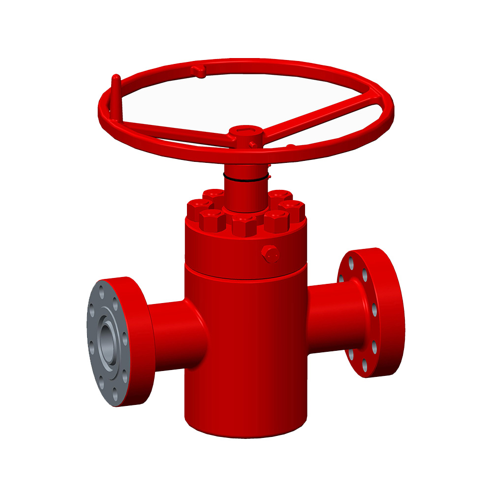 GATE VALVE FC API 6A Oilfield Gate ValveAPI 6A gate valve for oil, gas, and mud service, covering 2-1/16–9 in. sizes with 2000–10000 PSI ratings.View Product →
Wedge, parallel and seat variations
Conclusion: the gate shape and seat detail predict how the valve handles temperature, distortion and abrasives.
A solid wedge is one piece, simple and inexpensive, and fine in general service, though it can stick after thermal cycling. A flexible wedge has a slit that lets the disc flex and follow the seats, which is why it appears in high-temperature work. A split wedge uses two halves on a ball joint and self-aligns, so installation orientation matters less. Metal seats faced with 13Cr or stellite tolerate abrasives and heat but demand higher closing torque; resilient PTFE seats seal with less effort but have a firm temperature ceiling.
What the cross-section tells you before installation
Conclusion: the cutaway answers three installation questions — flow direction, stem orientation and whether the valve can be serviced in place.
- Flow direction. Most gate valves are bidirectional, but a marked preferred direction usually reflects seat loading or a drain arrangement, and it is worth following on mud service.
- Stem orientation. Handwheel up where there is room, or a bevel gear and side-mounted handwheel where there is not. Actuated valves need clearance above the bonnet for the full cylinder stroke.
- Cavity and drain. A closed gate traps pressure in the body cavity; a drain or vent port on the drawing tells you it can be bled safely before the bonnet is opened.
- Service access. Repacking space and bonnet bolt clearance are drawn to scale more often than you would expect. If the drawing shows no room for a wrench, the field will find that out for you.
Flow-control decisions like these are covered in more depth in our note on how gate valves control flow in oil pipelines.
 GATE VALVE FLS API 6A Gate Valve for Oilfield Flow ControlAPI 6A gate valve for oil, gas, and mud media, with 1-13/16 to 7-1/16 in. sizes and pressure ratings to 20000 PSI.View Product →
Failure points the diagram helps you predict
Conclusion: the same cutaway that shows how the valve seals also shows every path by which it can fail.
- Seat and gate scoring, caused by throttling or by abrasive solids moving at speed.
- Packing leakage along the stem, worsened by a scored stem surface.
- Body-to-bonnet joint leaks, the most common external leak on bolted bonnets after thermal cycling.
- Sticking wedges in high-temperature service, when the body expands faster than the disc.
- Thread wear on non-rising stems, where the operating thread sits inside the process fluid.
- Cavity overpressure when a closed gate traps liquid and a heat trace does the rest.
None of that is visible from outside the valve. All of it is visible in a decent cross-section drawing.
Frequently asked questions
Is a gate valve diagram the same as a cross-section?
Usually yes. In a maintenance or datasheet context the diagram is the cutaway cross-section. On a P&ID or in a control narrative, the same phrase means the bowtie symbol. Ask which document is on the table before the meeting starts.
Can you throttle a gate valve?
You can, and nothing breaks immediately, but you should not. A partly open gate exposes the seats to high-velocity flow and vibration, and the disc can chatter against its guides. Gate valves are isolation valves: fully open or fully closed.
Why is the gate valve symbol shaped like a bowtie?
The two triangles represent the two seat-to-gate interfaces, and the line through the middle is the straight-through flow path. The symbol really is the cross-section diagram reduced to its two most important features.
Matching the drawing to the valve you are buying
Conclusion: use the diagram to ask better questions, then confirm the answers against real model data.
If the drawing shows a flexible wedge, a backseat shoulder and a bolted bonnet, while the quotation lists a solid wedge and a welded bonnet, you are comparing two different valves. That mismatch is one of the most common reasons a first delivery is rejected at the yard. For oilfield work the fastest check is to hold the cutaway against the model page: FC and FLS gate valves follow the classic bolted-bonnet, rising-stem layout used on wellheads and manifolds, while hydraulic gate valves replace the handwheel with a cylinder for remote or emergency operation. If the equipment is new to you, background reading on what a gate valve is and why it matters in oil extraction fills in the field context.
 GATE VALVE HYDRAULIC API 6A Oilfield Gate ValveAPI 6A hydraulic gate valve for oil, gas, and mud service, offered in 1-13/16 to 7-1/16 in. sizes and up to 20000 PSI.View Product →