English
 русский
A 13-5/8 in, 5,000 psi casing head bolted to a 10,000 psi casing spool is a mismatch that appears at the first pressure test, not in the catalogue. That is where most wellhead problems start: at a flange face where parts with different ratings, material classes or temperature ranges were joined on the assumption that they would fit.
Conventional wellhead systems are still the right answer for most land wells, workovers and shallow-water platforms. Their strength is modularity. Every pressure barrier is a separate, independently rated, independently replaceable component, so the stack can be specified stage by stage as the well is drilled and repaired one piece at a time.
The cost of that flexibility is height, weight, more flange make-up and more potential leak paths. What follows is how the system is built, how to specify it, and where it wins or loses against a compact wellhead.
Content
- What Counts as a Conventional Wellhead System
- How the Stack Is Built, Stage by Stage
- Conventional vs Compact: Choosing on Real Numbers
- Matching the Stack to the Completion
- Pressure Control Above the Tree
- Specification Checklist Before You Order
- Installation, Testing and Maintenance
- Frequently Asked Questions
What Counts as a Conventional Wellhead System
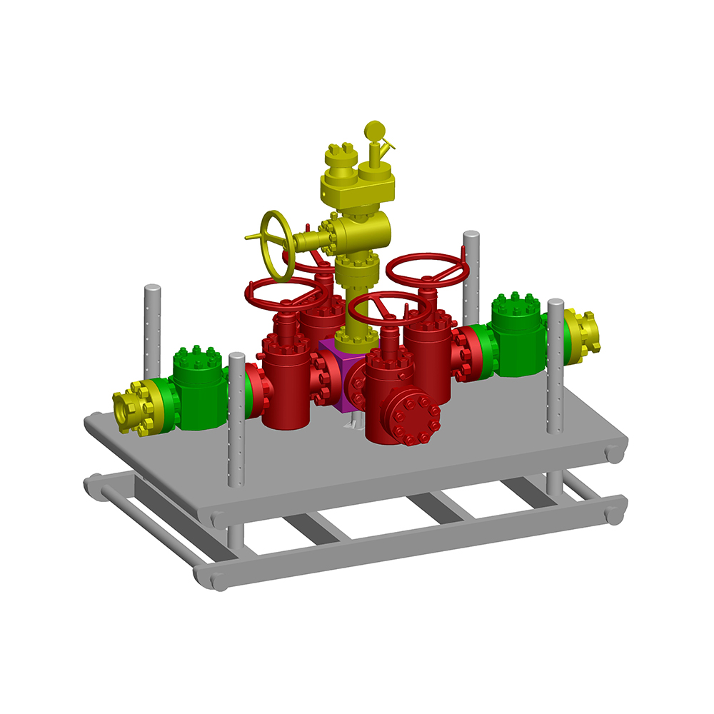
A conventional wellhead system is a stack of separate, bolted-together pressure-containing components — a casing head, one or more casing spools, a tubing head spool and a Christmas tree — each with its own API 6A pressure rating, temperature class and material class.
The term separates this architecture from a compact or monobore wellhead, where the same barriers are machined into fewer, larger bodies. In a conventional stack each component is built around the casing or tubing string it supports and seals, so the assembly behaves as a system: working pressure is set by the weakest link, not by the strongest part.
| Component | Role in the stack | Specify by |
|---|---|---|
| Casing head | Lands and seals the surface casing and carries everything bolted above it | Casing size and weight, top flange size and rating, outlets |
| Casing hanger | Suspends the next casing string and seals the annulus between strings | Slip or mandrel type, load capacity, seal material |
| Casing spool | Adds one barrier and one outlet per string as the well deepens | Number of spools, bore, outlet layout, rating step-up |
| Tubing head spool | Moves the stack from drilling to completion and supports the hanger | Single or dual completion, ESP clearance, outlets |
| Tubing hanger | Suspends production tubing and seals the tubing-to-head annulus | Mandrel or slip type, elastomer or metal seal, ESP variant |
| Christmas tree | Final pressure control: master, wing and swab valves plus a choke | Valve arrangement, choke type, rating, trim material |
How the Stack Is Built, Stage by Stage
Conventional wellhead systems are assembled in the order the well is drilled, and each new spool should be rated at least as high as the one beneath it. Any other order creates a barrier weaker than the well it is supposed to control.
The casing head and its hanger
The casing head is the anchor of the assembly: it lands on the surface casing, carries everything bolted above it and provides the first outlets for returns, monitoring or a choke line. A surface hole usually starts with a 13-3/8 in or 20 in body rated 2,000 to 5,000 psi, stepping up to 10,000 psi for deeper or higher-pressure programs. The hanger inside it either slips onto the casing as it is lowered or is a mandrel type made up on the string; slip hangers suit strings that must be cut and landed, while mandrel hangers give a more controlled seal where pressure integrity matters more than running speed.
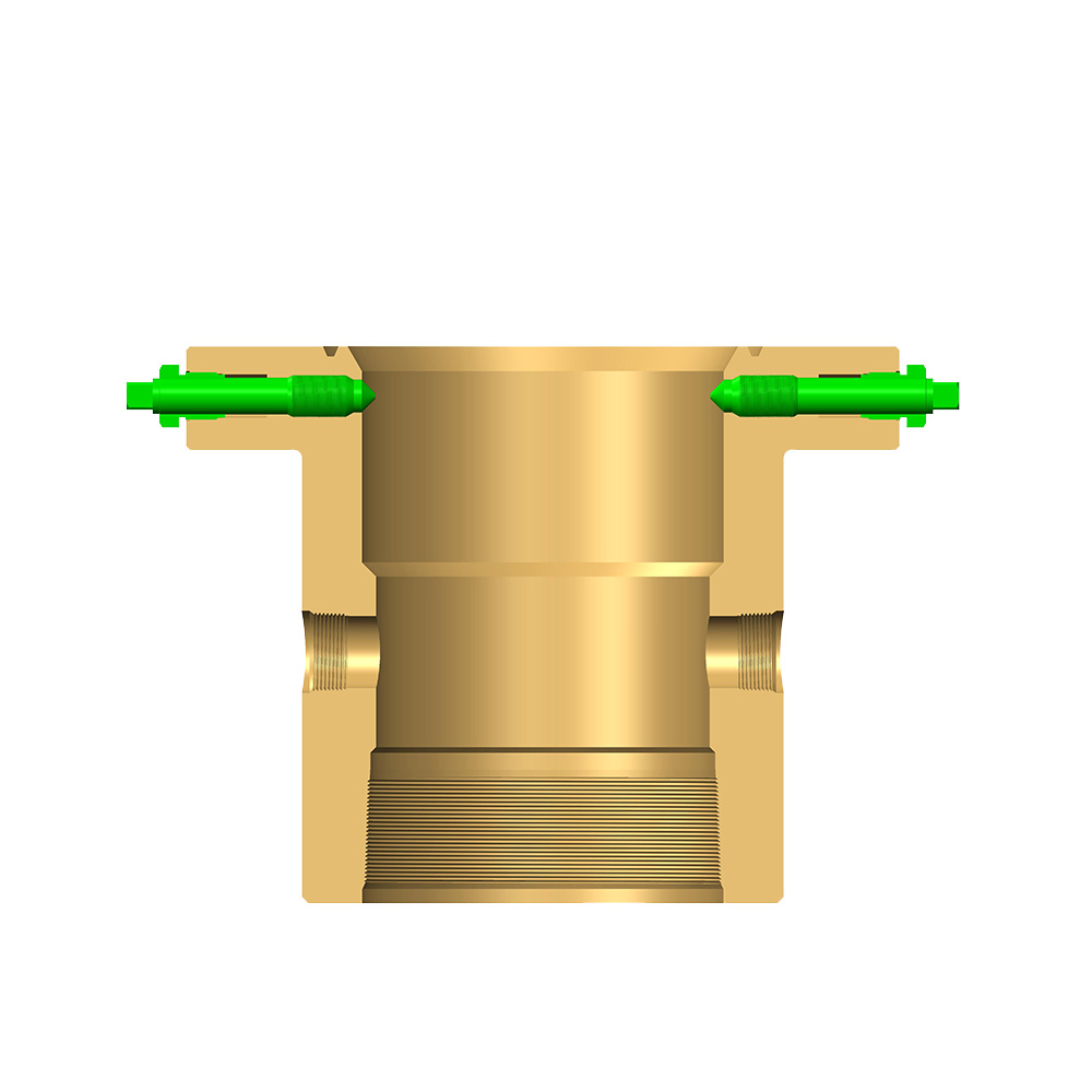 Csg Casing Head for Wellhead Casing Head AssembliesCsg casing head product entry under wellhead casing head assemblies; useful for identification and inquiry, while nearby text discusses anchoring, hangers, and stacked pressure barriers.View Product →
Casing spools and the pressure step-up
Every spool bolted on adds one barrier and one outlet, which is what allows the stack to grow with the well. A land sequence might run from a 13-5/8 in, 5,000 psi casing head to an 11 in, 10,000 psi spool and on to a 7-1/16 in, 15,000 psi tubing head, but the order follows the casing program rather than a catalogue. Each stage is normally shell-tested at 1.5 times its rated working pressure before the next hole section is drilled, and the test chart belongs in the well file alongside the material certificates.
Conventional vs Compact: Choosing on Real Numbers
Conventional stacks cost less per component and can be repaired in place, while compact wellheads save rig time and deck space. Which one wins depends on how many wells are being drilled and what lifting capacity is available.
| Factor | Conventional stack | Compact wellhead |
|---|---|---|
| Architecture | Separate bodies stacked and bolted, one barrier per spool | Fewer, larger bodies with barriers machined in |
| Height and weight | Taller and heavier, with more flange make-up | Shorter and lighter, with fewer connections |
| Flexibility | Components can be re-rated, repaired or replaced individually | Configuration fixed at manufacture |
| Cost profile | Lower per component, more parts to order and track | Higher per body, fewer interfaces to manage |
| Best fit | Land wells, workovers, stepwise drilling programs | Offshore templates and batch drilling |
The offshore case is where the gap is widest. On a template where several wells are batch-drilled, avoiding repeated flange make-up saves hours per well that compound across the program. That advantage only holds if the platform crane, the drilling schedule and the completion design support a monobore body. On a single land well served by a modest workover rig, the ability to replace one spool usually outweighs the assembly time.
Matching the Stack to the Completion
A wellhead sized for a single-string oil producer will not fit an ESP well or a dual completion, so the completion design has to be fixed before the tubing head is ordered.
Tubing head and hanger selection
The tubing head spool is the handover point between drilling and production: it supports the tubing hanger, seals the tubing-to-head annulus and carries outlets for annulus monitoring, gas lift or circulation. Mandrel hangers are standard for most completions, with dual-string and slip versions where two strings share one head. On ESP wells the adapter and hanger must clear the cable penetration and the pump outside diameter, or the completion will not pass through.
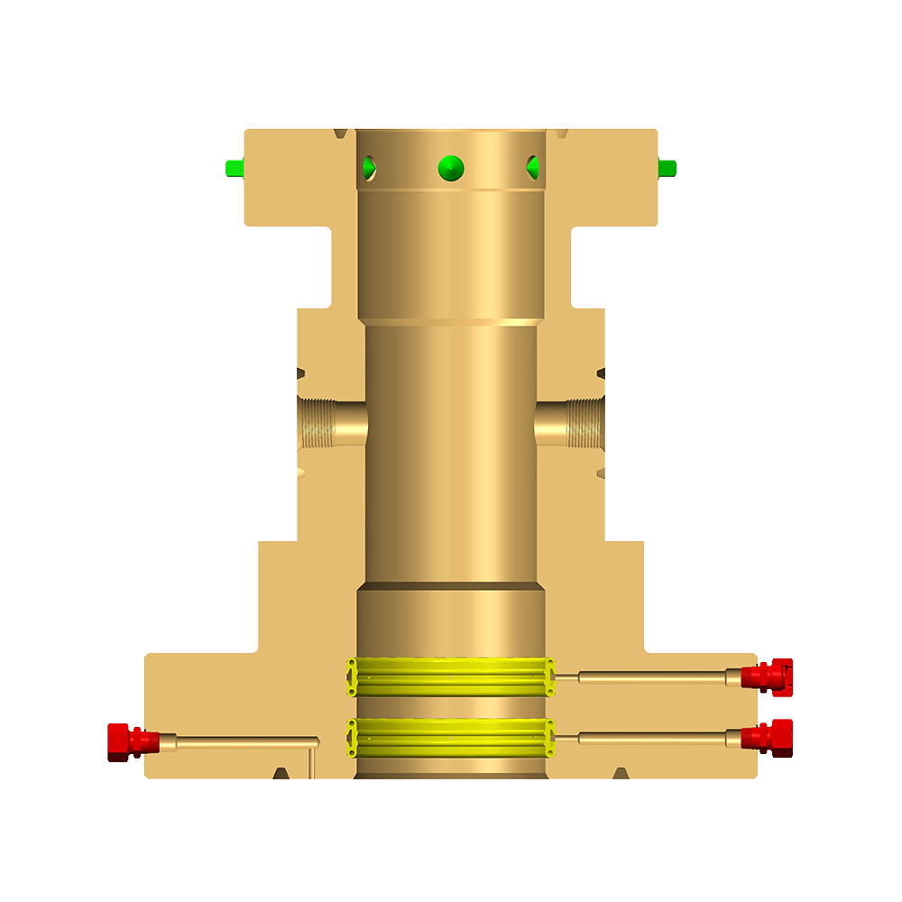 Tubing Head Spool for Wellhead Completion AssembliesProduct detail page identifies Tubing head spool under wellhead tubing head assembly, supplied by Jiangsu Zhonglin Oil Equipment; contact option available.View Product →
Temperature, sour service and material class
Material class and temperature class are engineering decisions, not paperwork. A well producing 3 mol% H2S at 120 °C is a different specification from a dry gas well at 60 °C, and hardness limits, elastomer choice and NACE-compliant metallurgy have to be agreed before the bodies are machined. Changing them later means recutting or scrapping the component.
Pressure Control Above the Tree
Pressure control does not stop at the Christmas tree. The surface safety valve is held open by a hydraulic or pneumatic supply and closes when that supply is lost, which makes the actuator and the control panel the real determinants of shut-in time. Chokes absorb the pressure drop that would otherwise destroy downstream pipework: a positive choke where a fixed restriction is acceptable, an adjustable choke where flow must be trimmed as reservoir pressure falls. The panel ties wellhead pressure to the valve, and its pilot settings, response time and manual override decide how quickly the stack closes. The mechanics of that link are covered in this note on how a control panel communicates with a remote safety valve.
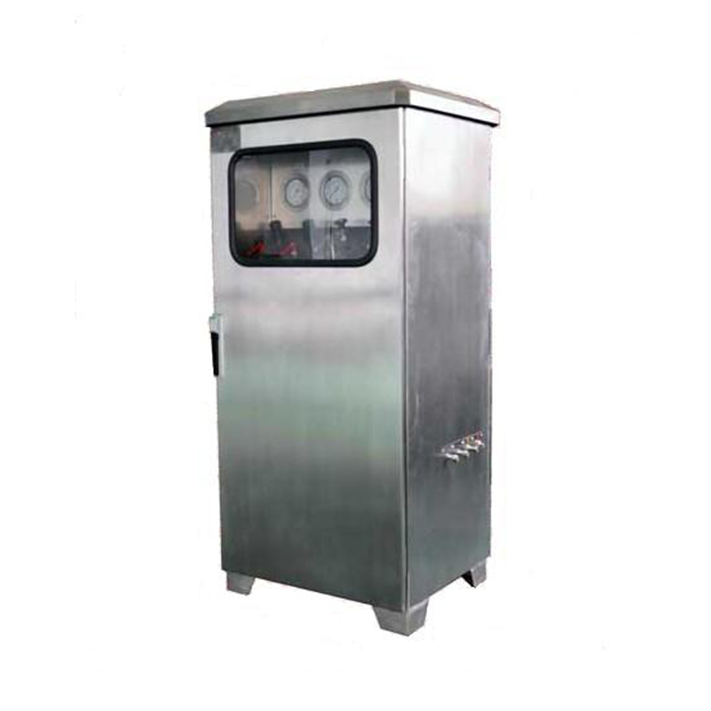 Wellhead Emergency Shutdown Control Panel for Safety ValvesControl panel for remote emergency shutdown of wellhead safety valves; API 6A, sizes 1-13/16 to 7-1/16 in, and 2,000 to 15,000 PSI ratings.View Product →
Specification Checklist Before You Order
Most wellhead disputes trace back to details that were never written into the enquiry. Confirm all of the following before the purchase order goes out.
- Pressure rating at every interface, not only at the top flange.
- Casing and tubing sizes, weights and thread types for each hanger.
- Temperature class and material class for each body, matched to produced fluids.
- API 6A product specification level (PSL) and performance requirement (PR1 or PR2).
- Outlet configuration: studded or flanged, size, rating and valve compatibility.
- Test and documentation requirements: shell and seat tests, material certificates, traceability.
- Spares: seal kits, hanger packing, repair kits and the tools needed to change them.
- Lead time, packaging and lifting points, particularly for large-bore casing heads.
Supplier certification is the quickest screening filter. An API 6A monogram and ISO certification show that the manufacturer's quality system covers design, manufacture and testing, but they do not replace the specification review above, because a certified supplier can still build exactly the wrong wellhead.
Installation, Testing and Maintenance
Field failures on conventional wellheads are usually installation or maintenance problems rather than manufacturing defects. A consistent sequence prevents most of them.
- Check flange faces, ring gaskets and studs against the drawing before make-up.
- Torque studs in a controlled cross pattern to the manufacturer's figures, not to a rig crew estimate.
- Pressure-test stage by stage, hold the test and record the chart.
- Confirm the hanger is landed and the seal is energised before drilling out the next shoe.
- Replace elastomer seals on the recommended interval, with the repair kit already on site.
- Re-check control panel settings after any workover that changed wellhead pressure.
Inspection intervals normally come from the operator's well integrity policy rather than from the wellhead itself, and any interval is only credible if the seal kits and retrieving tools are on location when it falls due.
Frequently Asked Questions
Is a conventional wellhead still competitive against a compact wellhead?
Yes, on land and in workover-heavy programs. The compact design wins on offshore templates and batch drilling, where deck space and rig time dominate; the conventional stack wins wherever a single component has to be replaced without pulling the whole assembly.
How do I choose the pressure rating for each casing spool?
Match it to the maximum anticipated surface pressure of the next hole section, and never let it fall below the rating of the component underneath. Rating steps are usually 2,000, 3,000, 5,000, 10,000 and 15,000 psi.
Should I use a slip-type or a mandrel casing hanger?
Use slip-type when the casing must be cut and landed or when running time matters most; use mandrel-type when seal integrity and load control are the priority. Both fit the same casing head or spool, so the choice can be made per string.
What documentation should ship with a wellhead?
At minimum: material certificates, API 6A monogram and traceability records, hydrostatic and gas test charts, assembly drawings, torque tables and a seal kit list with part numbers.
Conventional wellhead systems earn their place by being boring in the right way. Every barrier is visible, individually rated and individually replaceable, and the assembly can change as the well changes. Specify the ratings interface by interface, match the hangers to the completion, and keep the test charts and spare seals where the crew can find them — that is what turns a stack of flanges into a dependable wellhead.