The choke valve, also known as the throttle valve or choke valve, is a key control device in the oil and gas industry and other high-pressure fluid systems. Its core function is to accurately control the flow and pressure of the fluid, especially under the harsh working conditions of high pressure difference, solid particles or gas-liquid multiphase flow.
1. The core function and purpose of the choke valve
Control wellhead pressure: This is the most important function. In the early stage of oil and gas well production or in high-pressure wells, the bottom hole pressure is much higher than the tolerance of the downstream processing system. The choke valve reduces the fluid pressure to a safe operating range by creating an adjustable resistance (pressure drop) to protect downstream pipelines, separators and other equipment.
Adjust production: By changing the valve opening (throttling area), the volume flow of the oil and gas well or pipeline is accurately controlled to achieve production allocation targets or test requirements.
Prevent cavitation/flash: Under certain working conditions (such as sudden pressure drop leading to liquid vaporization), a properly designed choke valve (such as multi-stage throttling) can slow down the pressure drop rate, reduce or eliminate destructive cavitation and erosion of the valve.
Well control safety: In drilling, completion and well repair operations, the adjustable choke valve is a key component of the blowout preventer group, used to implement well killing operations, control well kicks or blowouts, and is one of the last barriers to well control safety.
Flow assurance: Controlling flow helps to slow down problems such as hydrate formation, wax deposition or scaling.
Testing and metering: Provide stable back pressure and flow conditions during production testing or flow metering.
2. Main types of choke valves
According to their structure and adjustment method, they are mainly divided into two categories:
Fixed choke valve (Fixed Choke)
Principle: An unadjustable throttling element is installed inside (usually a ceramic or carbide bushing with a precise drilling size - Bean).
Features:
Simple structure, durable and relatively low cost.
Strong erosion resistance (especially ceramic or carbide bushings).
Flow/pressure control is fixed. If it needs to be changed, the machine needs to be stopped to replace the throttling bushing with different apertures.
Application: Mainly used in situations where long-term stable flow/pressure is required, or as a backup/auxiliary throttling element for adjustable choke valves. Also commonly used in test processes.
Adjustable choke valve (Adjustable / Variable Choke)
Principle: The opening (throttling area) between the valve core and the valve seat is continuously adjusted through an external operating mechanism (manual, hydraulic, pneumatic or electric) to change the flow and pressure drop.
Core structure (common types):
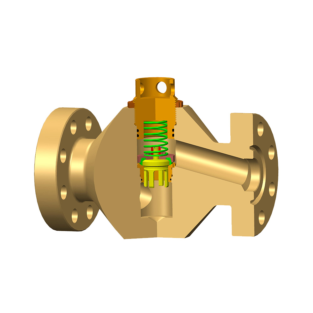
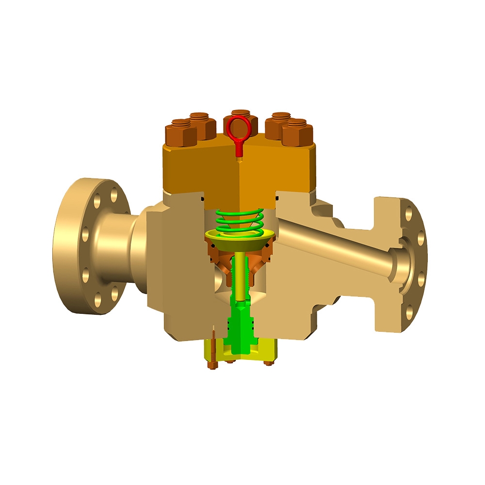
Needle valve type: A conical needle valve (Needle) is inserted into the matching valve seat (Seat) hole, and the axial movement of the needle valve changes the annular throttling area. High precision, suitable for clean fluids.
Cage type/multi-hole type: The valve core (plunger type or sleeve type) moves in a cage (Cage) with special holes to change the flow area. The hole design (size, shape, number distribution) on the cage can optimize flow characteristics, reduce noise, cavitation and erosion. The most widely used.
Gate/knife gate type: Similar to the gate valve, but with a specially designed cutting edge, it can provide cut-off and throttling functions in slurries containing solid particles.
Features:
It can continuously and finely adjust the flow and pressure during operation, and respond quickly.
High degree of automation, easy to integrate into control systems (such as SCADA, DCS).
The structure is relatively complex, the cost is high, and it is more sensitive to wear (regular maintenance is required).
Drive mode:
Manual: Operated by handwheel and gearbox. Simple and reliable, low cost, suitable for infrequent adjustment or standby.
Hydraulic/pneumatic: Use hydraulic oil or compressed air to drive the actuator. Provide strong thrust, explosion-proof, suitable for remote or harsh environments. Most common.
Electric: The actuator is driven by a motor. High control accuracy, convenient signal transmission, explosion-proof and reliability need to be considered.
3. Key Design Features and Challenges
The choke valve works under extreme conditions, and the design must address the following challenges:
Erosion resistance:
Hardening of key components: Surface hardening of valve core, valve seat, and cage (such as tungsten carbide spraying, nitriding, and surfacing of Stellite alloy).
Selection of superhard materials: ceramics (alumina, silicon carbide), tungsten carbide alloy bushings or components.
Flow channel optimization: Guide the fluid smoothly through the throttling area to avoid turbulence and direct impact.
Cavitation resistance:
Multi-stage pressure reduction: Disperse the total pressure drop in multiple series-connected small pressure drop stages (multi-stage throttling cage) to prevent the single-point pressure from dropping below the liquid vapor pressure.
Cavitation resistance cage design: Special hole types (such as labyrinth type) promote the collapse of bubbles in the high-pressure chamber, reducing direct impact on the metal surface.
Material selection: Hard materials are more resistant to cavitation damage.
Sealing:
Metal-to-metal sealing: The valve core and valve seat are made of hard alloy to ensure reliable sealing and long life under high pressure difference. Main seal type.
Auxiliary seal: Valve stem packing (such as graphite, PTFE) prevents external leakage. API 6A valves require strict sealing levels (such as PR2, PR2F).
Operating force and control:
Balanced design: Reduce the thrust/torque required for valve operation (especially for large-diameter high-pressure differential valves).
Actuator selection: Sufficient thrust to overcome fluid force and friction to ensure accurate and reliable positioning.
4. Typical application scenarios
Oil and gas production:
Wellhead throttling of oil wells, gas wells, and condensate gas wells (control wellhead pressure and adjust production).
Test separator inlet pressure control.
Water injection/gas injection well flow control.
Gas volume control in artificial lift (such as gas lift) systems.
Drilling and completion:
BOP core components, used for well killing and throttling.
Flow/pressure control in drilling and completion fluid (mud) circulation systems.
Flow and pressure control during formation testing (DST).
Other industries:
High-pressure steam systems in chemical plants and power plants.
Slurry pipelines in mines.
High-pressure water jet systems.
5. Key considerations for selection
Choosing the right choke valve is crucial and requires evaluation of:
Fluid properties: oil, gas, water, multiphase flow, sand content, H₂S/CO₂ content (material requirements), temperature, viscosity.
Operating parameters:
Upstream pressure (P1)
Downstream pressure (P2)
Expected pressure drop (ΔP = P1 - P2) - the most critical parameter
Maximum/minimum flow (Q)
Fluid temperature
Functional requirements: Is the main purpose to control pressure, flow, or both? Is frequent adjustment required? Is automatic control required?
Size and connection method: Pipeline size (NPS/DN), pressure level (such as ANSI Class, PN), flange standard (ASME, API, DIN) or butt welding connection.
Material grade: Valve body and trim materials must meet pressure, temperature, corrosion and erosion resistance requirements. Focus on the valve core, valve seat, cage/bushing material (such as 316SS, duplex steel, 625 alloy, tungsten carbide, ceramic). Follow NACE MR0175/ISO 15156 (sour service).
Actuation mode: manual, hydraulic, pneumatic, electric? How much thrust/torque is required? Is position feedback required?
Standards and specifications: It is crucial to follow industry standards:
API 6A: Wellhead and Christmas tree equipment specifications - the most core standard for upstream oil and gas, covering pressure levels, materials, design, testing, and documentation requirements (such as PSL, PR level).
API 14C/ISO 10418: Offshore platform safety system analysis, design and installation.
API 6D/ISO 14313: Pipeline valve specifications.
ASME B16.34: Valve flanges, threads and welding ends.
NACE MR0175/ISO 15156: Petroleum and Natural Gas Industry - Materials for H₂S-containing Environments in Oil and Gas Production.
6. Key Points for Operation and Maintenance
Operation:
Adjust slowly: Avoid sudden changes in flow/pressure that may cause shock to the system.
Avoid small opening: Extremely small opening increases the risk of erosion and cavitation. Understand the minimum recommended opening of the valve.
Monitoring parameters: Pay close attention to upstream and downstream pressure, temperature, flow changes and abnormal noise/vibration.
Maintenance:
Regular inspection:
External leakage (stem packing, flange connection).
Whether the actuator operates smoothly.
Whether the pressure gauge and position indicator are normal.
Preventive maintenance:
Inspect/replace the valve core, valve seat, cage/bushing and other wearing parts according to the manufacturer's recommended cycle.
Lubricate moving parts.
Inspect/replace the valve stem packing.
Spare parts: Reserve key wearing parts (especially spare hand valves for fixed choke valves).