A gate valve works by raising or lowering a flat or wedge-shaped gate (disc) through the flow path via a threaded stem and handwheel — when the gate is fully raised, the bore is completely unobstructed and flow passes with minimal pressure drop; when fully lowered, the gate seats against two parallel or wedge-shaped seat faces to create a bidirectional, leak-tight shutoff. In oil extraction, gate valves are the dominant on/off isolation device across wellheads, Christmas trees, flowlines, and production manifolds because they combine full-bore flow with the pressure integrity needed for crude oil, natural gas, and produced water service at ratings from 2,000 psi (API 6A Class 2K) to 20,000 psi (Class 20K) and temperatures from -60°C to +180°C.
Content
- Why Gate Valves Are the Standard in Oil Production Systems
- How a Gate Valve Works: The Internal Mechanism Step by Step
- What Types of Gate Valves Are Used in Oil Extraction?
- How Different Gate Valve Types Compare in Oil Extraction Service
- How Does a Gate Valve Compare to Other Valve Types in Oil Production?
- Which Standards Govern Gate Valves in Oil Extraction?
- How Are Gate Valves Actuated in Oil Production Systems?
- Frequently Asked Questions: How a Gate Valve Works in Oil Extraction
- Q: Why can a gate valve not be used for throttling flow on a wellhead?
- Q: What causes a wellhead gate valve to fail to close fully?
- Q: What is the difference between a rising stem and non-rising stem gate valve in oil field service?
- Q: How often should gate valves on a Christmas tree be exercised?
- Q: What materials are used for gate valves in sour (H2S) oil production service?
- Q: Can a gate valve be repaired in situ on a live wellhead?
- Summary: Understanding How a Gate Valve Works in Oil Extraction
Why Gate Valves Are the Standard in Oil Production Systems
Gate valves dominate oil extraction piping systems because their full-bore, straight-through flow path creates virtually zero pressure drop in the fully open position — a critical advantage when every psi of wellhead pressure translates directly to production rate and lift efficiency. In contrast, globe valves of the same nominal bore introduce a pressure drop coefficient (Cv) typically 5–10 times higher, making them unsuitable as primary isolation valves on high-volume production lines.
The global oil and gas valve market was valued at approximately USD 5.4 billion in 2023, with gate valves representing the single largest product category by installed unit count across upstream production facilities. A typical onshore wellpad may contain 40–80 gate valves per well across the Christmas tree, flowline, and production header. A deepwater subsea tree may contain 12–24 gate valves of various bore and pressure ratings, each required to function reliably for 20–25 years with minimal intervention access.
Understanding how a gate valve works — its internal mechanics, sealing principle, material requirements, and failure modes — is therefore fundamental knowledge for petroleum engineers, production technicians, and valve specification engineers working in upstream oil and gas operations.
How a Gate Valve Works: The Internal Mechanism Step by Step
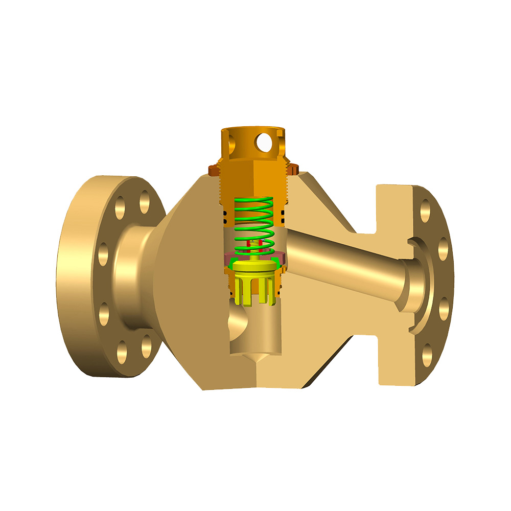
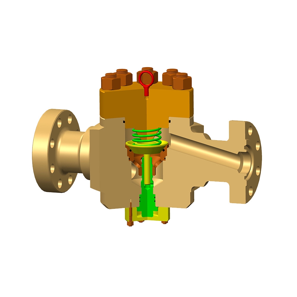
The operating mechanism of a gate valve converts rotational motion at the handwheel or actuator into linear motion of the gate through a threaded stem, and the position of the gate within the valve body determines whether flow is fully open, fully closed, or blocked. The five main components involved in this mechanism are:
- Body and bonnet: The pressure-containing shell. In oil field service, the body is typically AISI 4130 or 8630 alloy steel, Inconel, or duplex stainless steel depending on the H2S and CO2 content of the produced fluid. API 6A specifies body material classes (AA through FF and HH) matched to the sour service severity.
- Gate (disc): The flat or wedge-shaped element that physically blocks or opens the flow path. In slab gate valves — the most common type on wellheads — the gate is a rectangular metal slab with a circular port that aligns with the bore when open and moves out of the bore when closed.
- Seats: Two annular sealing surfaces, one on each side of the gate, that the gate presses against when in the closed position. In metal-seated designs, the seats are typically hard-faced with Stellite or tungsten carbide to resist erosion from sand-laden production fluids. Soft-seated designs use PTFE or elastomer inserts for tighter shutoff at lower differential pressures.
- Stem: The threaded rod that connects the handwheel or actuator to the gate. In a rising-stem design, the stem moves axially upward as the valve opens, providing a visual position indicator. In a non-rising-stem design, the stem rotates in place and the gate travels on internal threads — preferred where vertical headroom is limited, such as on a Christmas tree with a BOP stack above.
- Packing and stem seal: The dynamic seal between the moving stem and the bonnet that prevents wellbore pressure from escaping along the stem. In sour gas service (H2S above 0.0003 MPa partial pressure per NACE MR0175), packing must be elastomers compatible with H2S — typically HNBR (hydrogenated nitrile rubber) or AFLAS — rated for the full wellhead pressure.
The Open-Close Cycle in Oil Field Operation
Turning the handwheel clockwise closes the valve (gate descends), and counterclockwise opens it (gate ascends) — the universal convention confirmed by the mnemonic "righty-tighty, lefty-loosey," though oil field practice always verifies direction before operation on a live well. The operational sequence on a wellhead gate valve proceeds as follows:
- Opening stroke: Counterclockwise rotation of the handwheel causes the stem to rise (rising-stem type). The gate attached to the stem bottom lifts out of the flow path. The port in the slab gate aligns with the valve bore, creating a straight-through flow passage with internal diameter equal to the nominal pipe bore. Full open requires typically 10–40 turns depending on stem pitch and valve size.
- Full open position: The gate is retracted entirely into the bonnet cavity above the flow path. Wellbore fluid flows through the full bore with negligible turbulence or pressure drop — a key advantage for pigging operations and multiphase flow measurement.
- Closing stroke: Clockwise rotation lowers the gate into the flow path. As the gate approaches the seat, downstream pressure assists in driving the gate against the downstream seat (in downstream-seating designs). The final turns apply mechanical seating force through the stem thread, pressing the gate firmly against both seats to create the shutoff seal.
- Backseat: Most oil field gate valves incorporate a backseat — a secondary metal-to-metal seal between the stem and the bonnet that engages in the fully open position, isolating the packing from wellbore pressure. This allows packing replacement under pressure in an emergency, though this practice is performed only by trained personnel under strict safety protocols.
What Types of Gate Valves Are Used in Oil Extraction?
Oil extraction uses several distinct gate valve designs, each optimized for a specific function within the production system — and selecting the wrong type is a leading cause of premature valve failure and unplanned well interventions.
1. Slab Gate Valves (Parallel Slide Gate Valves)
Slab gate valves are the standard design on wellheads and Christmas trees, using a flat rectangular gate with a through-bore that aligns with the valve bore when open and is displaced sideways into the body cavity when closed. The gate is held against the downstream seat by line pressure in the closed position — a self-energizing sealing action that improves shutoff performance as wellbore pressure increases. Most API 6A wellhead valves from 2 inches through 7-1/16 inches nominal bore use this design. Pressure ratings up to 20,000 psi (138 MPa) are available, meeting the most demanding HPHT (high pressure high temperature) well requirements.
2. Expanding Gate Valves
Expanding gate valves use a two-segment gate assembly that expands radially as the valve reaches the fully open or fully closed position, forcing the gate segments against both the upstream and downstream seats simultaneously to create a bidirectional, double-block seal. This design virtually eliminates the cavity volume between the gate segments and the seats, making it highly resistant to debris accumulation — a critical advantage in sand-producing wells where standard slab gate cavities trap formation sand that prevents full closure. Expanding gates are commonly specified on master gate valves and swab valves of the Christmas tree where absolute shutoff reliability is non-negotiable.
3. Through-Conduit Gate Valves
Through-conduit gate valves maintain a smooth, full-bore flow path in both the open and closed positions, with the gate designed so that the body cavity never communicates with the pipeline bore — making them the required type for pipeline pigging operations and for applications where no cavity dead-volume is acceptable. In offshore production, through-conduit gate valves are specified on export pipeline isolation duties where inline inspection tools (intelligent pigs) must pass without obstruction. They are also preferred on heavy crude and waxy crude pipelines where trapped fluid in standard valve cavities would solidify during a shutdown and prevent reopening.
4. Subsea Gate Valves
Subsea gate valves are specially engineered slab or expanding gate designs for installation on seabed wellheads, manifolds, and pipeline end terminations (PLETs) at water depths up to 3,000 m, with operating lives of 25 years between service interventions. Key differences from surface valves include: pressure-compensated hydraulic actuators (to offset hydrostatic water pressure at depth), corrosion-resistant body materials (duplex or super duplex stainless steel, or 625 Inconel overlay), ROV-operable override torque interfaces, and qualification testing per API 17D to the full combined rating of pressure, temperature, and external hydrostatic head. A 4-1/16 inch 10,000 psi subsea gate valve for a deepwater Christmas tree typically weighs 200–400 kg and costs USD 25,000–80,000 depending on material grade and actuator specification.
How Different Gate Valve Types Compare in Oil Extraction Service
The table below compares the four primary gate valve types used in oil production across the attributes most relevant to upstream operations.
| Gate Valve Type | Pressure Rating | Sand Resistance | Piggable | Bidirectional Seal | Typical Location | Relative Cost |
| Slab Gate | 2K–20K psi | Moderate | No | Downstream only (standard) | Wellhead, Christmas tree | Base reference |
| Expanding Gate | 2K–15K psi | High | No | Yes — both directions | Master gate, swab valve | 1.5–2x slab gate |
| Through-Conduit Gate | 600–2500 psi | High | Yes | Yes | Export pipelines, pig traps | 2–3x slab gate |
| Subsea Gate | 5K–20K psi | High | Configuration-dependent | Yes | Subsea tree, manifold, PLET | 5–20x slab gate |
Table 1: Comparison of gate valve types used in oil extraction across pressure rating, sand resistance, pigging capability, sealing direction, application location, and relative cost.
How Does a Gate Valve Compare to Other Valve Types in Oil Production?
Gate valves are optimized for on/off isolation duties in oil production and should never be used for flow throttling — when partially open, the gate vibrates in the flow stream, rapidly eroding the seats and gate faces, leading to premature seal failure. Understanding where gate valves are superior — and where they are not — prevents costly mis-specification.
| Valve Type | Flow Characteristic | Throttling Suitability | Pressure Drop (full open) | Piggable | Typical Oil Field Use |
| Gate Valve | On/Off only | No | Minimal | Yes (through-conduit type) | Wellhead isolation, block valves |
| Ball Valve | On/Off, fast-acting | Limited (V-port only) | Minimal | Yes (full-bore type) | Emergency shutdown, pig traps |
| Globe Valve | Throttling | Excellent | High | No | Wellhead choke (not standard globe) |
| Choke Valve | Throttling / control | Designed for it | High (by design) | No | Wellhead production rate control |
| Check Valve | Unidirectional auto | No | Low–Moderate | No | Injection lines, pump outlets |
Table 2: Comparison of gate valves against other valve types commonly used in oil production, by flow function, throttling suitability, pressure drop, and typical application.
Which Standards Govern Gate Valves in Oil Extraction?
API 6A (Wellhead and Christmas Tree Equipment) is the primary standard governing gate valves used directly at the wellhead, while API 6D governs pipeline gate valves and ASME B16.34 covers general-purpose industrial gate valves used in oil production facilities. Each standard defines different pressure classes, material requirements, testing protocols, and quality management expectations.
API 6A — Wellhead Gate Valves
API 6A defines the most rigorous performance and material requirements for gate valves in direct wellbore service, reflecting the safety-critical nature of wellhead integrity. Key provisions include:
- Pressure classes: 2,000 / 3,000 / 5,000 / 10,000 / 15,000 / 20,000 psi (13.8 MPa to 138 MPa). Each class has defined pressure-temperature ratings and corresponding wall thickness and material requirements.
- Material classes: AA (general service), BB (low temperature to -46°C), CC, DD (H2S service per NACE MR0175), EE (H2S + low temperature), FF, HH (high H2S, high temperature). A deepwater HPHT well may require Class EE or HH valves throughout the Christmas tree.
- Product Specification Levels (PSL): PSL 1 through PSL 4, with PSL 3G and PSL 4 requiring 100% non-destructive examination, full traceability of all materials, witnessed factory acceptance testing, and PR2 performance testing (including full-cycle pressure and temperature qualification).
- Temperature classes: K (-60°C to +82°C), L (-46°C to +82°C), P (-29°C to +82°C), R (-18°C to +121°C), S (-18°C to +149°C), T (-18°C to +177°C), U (-18°C to +180°C), V (2°C to +180°C).
API 6D — Pipeline Gate Valves
API 6D specifies requirements for pipeline gate valves in the gathering, transmission, and distribution of oil and gas, with pressure classes aligned to ASME B16.34 (Class 150 through Class 2500). Pipeline gate valves covered by API 6D must meet requirements for through-bore dimensions compatible with pipeline intelligent pigging, bidirectional sealing, anti-static design (to prevent electrostatic buildup in gas service), and low-emission fugitive emission packing per ISO 15848-1.
How Are Gate Valves Actuated in Oil Production Systems?
Gate valves in oil extraction are operated by handwheels, hydraulic actuators, pneumatic actuators, or electric actuators depending on the required closing speed, available energy source, and whether the valve is part of an emergency shutdown (ESD) system.
- Manual handwheel: Used for infrequently operated isolation valves on low-pressure flowlines and utilities. Typical operating torque for a 4-inch, 5,000 psi gate valve against full differential pressure is 200–600 Nm — within manual capability with a standard handwheel but marginal for larger, higher-pressure valves.
- Hydraulic actuator (fail-safe spring return): The standard actuation method for wellhead and Christmas tree gate valves. Hydraulic supply from the wellhead control panel (WHCP) opens the valve against spring pressure; loss of hydraulic pressure causes the spring to close the valve automatically — the fail-safe-closed (FSC) configuration required for ESD functions on producing wells. Typical opening hydraulic pressure: 140–210 bar (2,000–3,000 psi).
- Pneumatic actuator: Used on topside production platform gate valves where instrument air supply is available. Less common on wellhead gate valves where hydraulic fluid is already present for BOP and control functions. Fail-safe spring return available in the same FSC configuration.
- Electric motor actuator (EMA): Increasingly used on remote wellsites, onshore ESD valves, and above-water subsea production systems where electrical power is available but hydraulic infrastructure is not. Electric actuators require battery backup or UPS for ESD capability in power failure scenarios.
- Subsea hydraulic actuator: Deepwater subsea gate valves use pressure-compensated hydraulic actuators connected to the subsea umbilical from the surface facility. Actuation hydraulic pressure must overcome both the spring force and the external hydrostatic water pressure — at 3,000 m water depth, this adds approximately 300 bar (4,350 psi) of back-pressure on the return side of the actuator.
Frequently Asked Questions: How a Gate Valve Works in Oil Extraction
Q: Why can a gate valve not be used for throttling flow on a wellhead?
Throttling a gate valve — holding it partially open to restrict flow — is prohibited in oil field practice because the high-velocity jet of produced fluid through the partially open gate causes severe erosion of the gate face and seat surfaces within hours to days of operation. Sand-laden crude oil or gas at wellhead velocities of 5–30 m/s acts as an abrasive cutting medium against the exposed gate metal. A gate valve that has been throttled typically shows seat damage that prevents full shutoff within a single operating period. Dedicated choke valves — designed with replaceable tungsten carbide or ceramic trim — are used for all flow rate control functions on the wellhead, while gate valves are operated only fully open or fully closed.
Q: What causes a wellhead gate valve to fail to close fully?
The three most common causes of wellhead gate valve failure to close fully are sand accumulation in the gate cavity, erosion damage to the gate or seats, and hydraulic actuator failure due to loss of supply pressure or spring fatigue. Sand accumulation is particularly insidious — formation sand that enters the body cavity during production periods can compact over weeks to months, mechanically preventing the gate from fully descending to the closed position. This is why expanding gate valve designs (which minimize cavity volume) and regular valve exercising programs (operating the valve through its full stroke quarterly or as specified in the maintenance management system) are standard practice on sand-producing wells. Seat erosion from prior throttling damage is the other primary cause — a visually open seat groove on inspection is a definitive indicator that the valve requires refurbishment or replacement.
Q: What is the difference between a rising stem and non-rising stem gate valve in oil field service?
A rising stem gate valve provides a direct visual position indicator — the stem extends upward from the bonnet as the valve opens, and personnel can confirm open/closed status at a glance — while a non-rising stem valve uses a stem that rotates in place with the gate travelling internally on threads, providing no external visual position indication. In oil field service, rising stem designs are preferred on surface wellhead equipment where valve position confirmation is a safety requirement during well operations. Non-rising stem designs are used on Christmas trees with limited overhead clearance (particularly where a wireline BOP or coiled tubing BOP must be stacked above the tree) and on subsea valves where the stem extension would add unacceptable height to the tree assembly. All actuated gate valves in ESD service must have position feedback signals (open/closed limit switches) regardless of stem type, feeding back to the wellhead control panel and the facility safety system.
Q: How often should gate valves on a Christmas tree be exercised?
Industry best practice and most regulatory frameworks require Christmas tree gate valves to be fully exercised (operated through their full open-close-open stroke) at a minimum frequency of once per quarter for surface trees, with the results documented in the maintenance management system. Gate valves left in a fixed position for extended periods — particularly in sour or high-sand service — are at risk of gate-to-seat adhesion (particularly in H2S service where sulfide compounds can act as a bonding agent between metal surfaces) or sand packing that prevents movement. Some operators in high-sand wells exercise master gate valves monthly. API 6A and most operating company well integrity standards require that failure to achieve a successful full-stroke test triggers an immediate inspection and repair work order before the valve is relied upon for ESD function.
Q: What materials are used for gate valves in sour (H2S) oil production service?
Gate valves in H2S service must comply with NACE MR0175 / ISO 15156, which requires all wetted metallic components to have hardness values at or below HRC 22 (equivalent to approximately 250 HBW) to prevent sulfide stress cracking (SSC) — a form of hydrogen embrittlement that can cause catastrophic brittle fracture in harder steels. Acceptable body and bonnet materials include AISI 4130 normalized and tempered steel (at controlled hardness), 316L stainless steel for lower-pressure service, and duplex or super duplex stainless steel for combined sour and chloride service. Seat and gate hard-facing alloys must also be selected for SSC resistance — tungsten carbide with nickel binder (rather than cobalt binder) is specified for sour service seat overlays. Springs, bolting, and stem materials all require individual NACE compliance verification.
Q: Can a gate valve be repaired in situ on a live wellhead?
Limited in-situ maintenance is possible on live wellhead gate valves — specifically packing replacement using the backseat function — but gate or seat repair requires the valve to be isolated from wellbore pressure, which in practice means killing the well or installing a temporary isolation tool upstream. The backseat provision in API 6A gate valves allows the packing gland to be accessed at full wellbore pressure when the valve is in the fully open position with the backseat engaged, but this is a high-risk operation requiring a dedicated job safety analysis and permit-to-work. Any repair of the gate, seats, or body requires full pressure isolation. For this reason, onshore wells typically have at least a master gate valve and a wing valve on each flow path, providing redundant isolation capability so that one valve can be maintained while the other provides wellbore containment.
Summary: Understanding How a Gate Valve Works in Oil Extraction
Understanding how a gate valve works in oil extraction goes well beyond the basic open/close mechanism — it encompasses the sealing physics, material science of sour and erosive service, actuator engineering for fail-safe operation, API standard compliance, and the maintenance discipline required to keep these critical isolation devices functional over the life of the well.
- Slab gate valves are the standard workhorse for wellhead and Christmas tree isolation, offering full-bore flow with minimal pressure drop at pressure ratings from 2,000 to 20,000 psi.
- Expanding gate valves provide superior sand resistance and bidirectional sealing for master gate and swab valve duties on sand-producing wells.
- Through-conduit gate valves enable pipeline pigging and provide cavity-free sealing on export and gathering lines.
- Subsea gate valves extend these capabilities to deepwater environments with 25-year intervention-free service life requirements.
- All wellhead gate valves must be operated only fully open or fully closed, never throttled, exercised regularly, and specified to the correct API 6A material class and PSL for the well's pressure, temperature, and fluid composition.
For any petroleum engineer or production technician, a thorough understanding of how a gate valve works — and more importantly, how it fails — is among the most practically valuable items of technical knowledge for maintaining well integrity and production efficiency throughout the productive life of an oil or gas well.